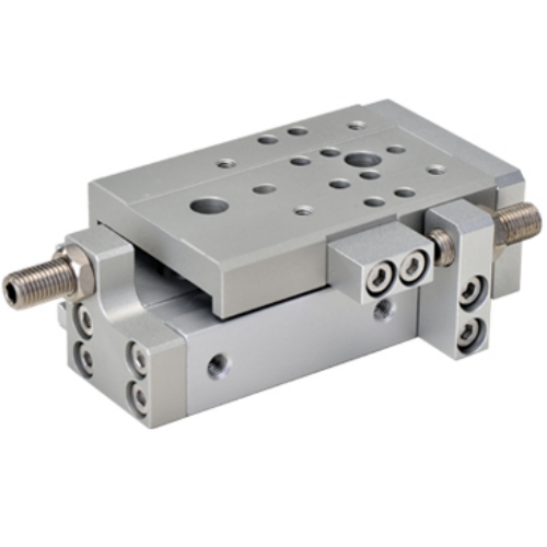
Airtac HLQ Dual-Axis Precision Slide Table Cylinder HLQ25X10SB
The AirTAC Airtac HLQ Dual-Axis Precision Slide Table Cylinder HLQ25X10SB is a genuine HLQ slide-table cylinder, 25 mm bore: a double-acting dual-rod air cylinder integrated with a ball-bearing guide so the table travels straight with high rigidity and low deflection. It delivers about 378 N of push at 0.5 MPa. A floating joint spares the rod from side torque; the magnet is fitted as standard.
- TypeSlide-table, double acting
- Guideball-bearing guide
- Bore25 mm
- Push thrust @0.5 MPa378 N
- Operating pressure0.15 - 0.7 MPa (22 - 100 psi)
- Port size1/8"
- CushionBumper (+ shock-absorber option)
- Magnet / sensorStandard; CMSH/DMSH/EMSH
- ThreadPT
About the Airtac HLQ Dual-Axis Precision Slide Table Cylinder HLQ25X10SB
A slide-table cylinder integrates an air cylinder with a linear guide so the moving table travels straight. This HLQ25X10SB model uses a ball-bearing guide for anti-rust, dust-proof operation, with a 25mm bore and 10mm stroke for higher thrust. The dual-rod design doubles the push, while a floating joint spares the rods from side torque.
This is a genuine AirTAC part with a standard magnet for sensor switches CMSH/DMSH/EMSH. We confirm exact thrust, dimensions, and load-moment from the datasheet or on-page table on request.
Airtac HLQ Dual-Axis Precision Slide Table Cylinder HLQ25X10SB Technical Specifications
| Model | Airtac HLQ Dual-Axis Precision Slide Table Cylinder HLQ25X10SB |
|---|---|
| Type | Slide-table cylinder, double acting, dual rod |
| Series / guide | HLQ (ball-bearing guide) |
| Bore | 25 mm |
| Push thrust @0.5 MPa | 378 N |
| Port size | 1/8" (PT thread) |
| Fluid | Air, filtered to 40 um |
|---|---|
| Operating pressure | 0.15 - 0.7 MPa (22 - 100 psi) |
| Proof pressure | 1.2 MPa (175 psi) |
| Temperature | -20 to 70 C |
| Speed range | 50 - 500 mm/s (meter-out) |
| Cushion | Bumper; shock-absorber / adjustable-stopper options |
| Magnet / sensor | Standard; CMSH, DMSH, EMSH |
Specifications follow the official AirTAC HL slide-table data. Max working pressure is 0.7 MPa. The table rides on an integrated linear guide — do not apply strong impact or large moment. Allowable load and moment are published as tables and curves, and overall dimensions vary per stroke — ask us and we confirm from the datasheet.
How to choose
Choose this 25mm bore for higher thrust. The ball-bearing guide (HLQ) is selected over cross-roller (HLS) when anti-rust and dust-proofing are priorities. Stroke fits within the bore table. This model includes shock absorbers on both ends (B) for smooth stops. Thread is PT. We route load and moment sizing to published tables and curves on request.
Applications
Pick-and-Place
Positions parts accurately during automated assembly using the integrated ball-bearing guide.
Small-Parts Transfer
Transfers small items between lines with smooth end-stop cushioning via shock absorbers.
Gripper Traverse
Drives a gripper back and forth reliably, absorbing impact at both ends of the stroke.
FAQ
What does the B adjuster mean on this model?
The B code specifies shock absorbers at both ends of the cylinder, ideal for absorbing impact and providing smooth stops at higher speeds.
Is load and moment data available for sizing?
Yes, allowable load, moment, and kinetic energy are confirmed from the published datasheet tables and curves on request.