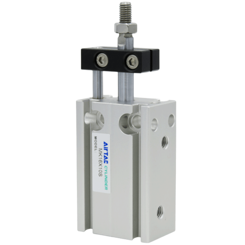
Airtac MK Series Multi-position Locking Cylinder MK16X60S
The AirTAC Airtac MK Series Multi-position Locking Cylinder MK16X60S is a genuine MK multi-mount cylinder (double acting), 16 mm bore. Its compact square body fixes from six directions and mounts side by side to save space. It delivers about 100.5 N of push force at 0.5 MPa. A bumper cushions the impact. As an MK unit a fixed rod stops the piston rod rotating.
- TypeMulti-mount, double acting
- SeriesMK (no-rotating)
- Bore16 mm
- Push thrust @0.5 MPa100.5 N
- Operating pressure0.15 - 1.0 MPa (22 - 145 psi)
- Port sizeM5x0.8
- CushionBumper
- MagnetWith magnet (sensor-ready)
- ThreadPT
- No minimum order. A single piece can be ordered.
- Ready in 3–5 business days. That is the time we take to process the order and hand it to the carrier. Transit time after that depends on the destination.
About the Airtac MK Series Multi-position Locking Cylinder MK16X60S
The AirTAC MK series is a compact multi-mount cylinder with a square body that fixes from six directions - front, back, left, right, top and bottom - so units can sit side by side to save space. This MK16X60S is double acting with a 16 mm bore and a 60 mm stroke, giving a theoretical push force of 100.5 N (86.4 N on the pull side) at 0.5 MPa. The bumper cushions travel at both ends, and magnetic-switch slots run around the body with high guide precision and no added lubricant.
This is a genuine AirTAC part. The MK family is the no-rotating type - a plate, brass bushing and fixed rod (typical - see the datasheet for bore-specific detail) stop the piston rod turning, unlike the standard MD series. The trailing S means the magnet is fitted, so magnetic switches can be used for position sensing; the plain MK16X60 is supplied without one. Operating range at this bore is 0.15-1.0 MPa (22-145 psi). As with all 60 mm bore-16 codes, confirm the variant and its dimensions from the datasheet with us before ordering.
Airtac MK Series Multi-position Locking Cylinder MK16X60S Technical Specifications
| Model | Airtac MK Series Multi-position Locking Cylinder MK16X60S |
|---|---|
| Type | Multi-mount cylinder, double acting |
| Series | MK (no-rotating) |
| Bore | 16 mm |
| Push thrust @0.5 MPa | 100.5 N |
| Port size | M5x0.8 (PT thread) |
| Magnet | With magnet (S) |
| Fluid | Air, filtered to 40 um |
|---|---|
| Operating pressure | 0.15 - 1.0 MPa (22 - 145 psi) |
| Proof pressure | 1.5 MPa (215 psi) |
| Temperature | -20 to 70 C |
| Speed range | 30 - 500 mm/s |
| Cushion | Bumper |
| Mounting | Fix from 6 directions; mountable side by side |
Specifications follow the official AirTAC MD/MK multi-mount data. The front cover and piston are short, so avoid an over-long stroke. An optional high-temperature seal material extends the range to 0 to 150 C. Overall dimensions vary per stroke and allowable side-load is published as curves — ask us and we confirm from the datasheet.
How to choose
The 16 mm bore delivers about 100.5 N of push (86.4 N pull) at 0.5 MPa; choose a larger bore only if the load demands it. MK stops rod rotation; MD allows it. This unit is double acting. On stroke: the standard bore-16 double-acting table tops out at 50 mm, so this 60 mm code sits beyond the standard range - confirm it from the datasheet or ask us, and remember that short covers make an over-long stroke a poor fit for a compact design. The trailing S orders the magnet; drop it if no switch sensing is needed. Thread is PT as standard, with G available. Route side-load limits to us or the datasheet.
Applications
Pick-and-place with sensing
Drives a small gripper in a pick-and-place module. The fitted magnet lets magnetic switches in the body slots signal extend and retract positions, while the fixed rod keeps the part orientation stable.
Fixture clamp on a longer reach
Clamps parts in a fixture where the clamp point sits further from the body. The 60 mm stroke reaches over the part, and the no-rotating rod keeps the clamp pad from twisting under load.
Indexing pin with position check
Advances an indexing pin between machine stations, with switch sensing confirming the pin is fully out before the next cycle starts. Multiple units mount side by side on one rail.
FAQ
What is the difference between MK16X60S and MK16X60?
Only the magnet. The trailing S on MK16X60S means the piston carries a magnet, so magnetic switches fitted in the slots around the body can detect rod position. MK16X60 without the S has no magnet and cannot be sensed this way. Both are bore-16, 60 mm stroke, double acting, no-rotating MK cylinders with PT thread as standard (G available).
Anything to check before using a 60 mm stroke at bore 16?
Yes. The standard stroke table for 16 mm bore double-acting multi-mount cylinders tops out at 50 mm, so confirm this longer variant from the datasheet with us before ordering. Keep in mind that multi-mount cylinders use short covers, so an over-long stroke reduces their compact, side-by-side advantage, and allowable side-load figures should be taken from the datasheet rather than estimated.