Airtac SC Series Cylinder Catelog download
Compendium of SC Series
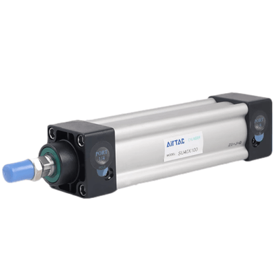
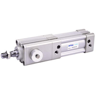
Standard cylinder manufactured by our enterprise

Convenient and fast fix sensor switch
Sensor switch can be directly fixed on the cylinder, which is convenient and fast. Bore size: 32, 40, 50, 63, 80, 100. The counterpart sensor switch type is: CMSG, DMSG, EMSG
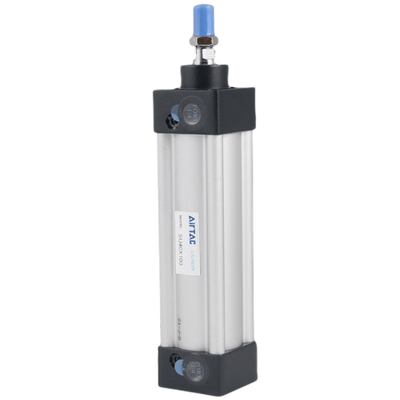
Tie-rod cylinder
The cylinder barrel and front/rear cap is jointed by tie rods with high reliability.
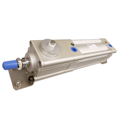
Adjustable air buffer
With adjustable air buffer on the front and back cover
Four kinds of cylinder joints

Multi-mounting accessories
| Knuckle | Knuckle | Floating Joint | Universal Joint |
|---|---|---|---|
| I Knuckle | Y Knuckle | LB | FA |
| FB | CA | CB | |
| TC |
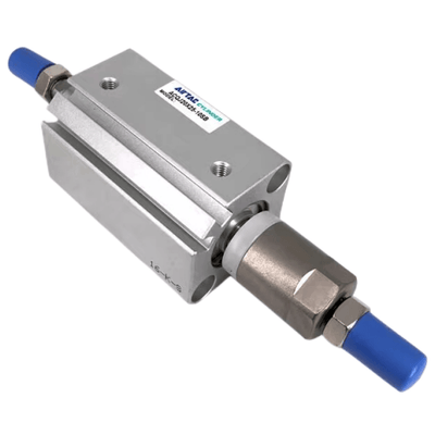
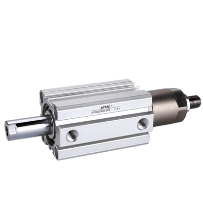
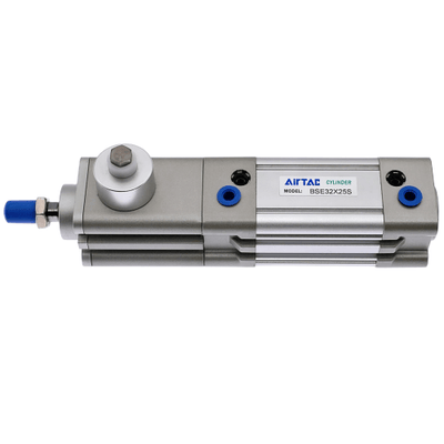
Multi-type cylinder
| SC: Double acting type | SCD: Double rod type | SCJ: Adjustable stroke type | SCT: Multi-position type |
| CA | CB | TC | TCM1 |
Criteria for selection: Cylinder thrust Installation and application!

| Unit: Newton(N) | |||||||||||||
|---|---|---|---|---|---|---|---|---|---|---|---|---|---|
| Bore size | Rod size | Acting type | Pressure area(mm) | Operating pressure(MPa) | |||||||||
| 0.1 | 0.2 | 0.3 | 0.4 | 0.5 | 0.6 | 0.7 | 0.8 | 0.9 | |||||
| 32 | 12 | Double acting | Push side | 804 | 80.4 | 160.8 | 241.2 | 321.6 | 402.0 | 482.4 | 562.8 | 643.2 | 723.6 |
| 32 | 12 | Double acting | Pull side | 690 | 69.0 | 138.0 | 207.0 | 276.0 | 345.0 | 414.0 | 483.0 | 552.0 | 621.0 |
| 40 | 16 | Double acting | Push side | 1256 | 125.6 | 251.2 | 376.8 | 502.4 | 628.0 | 753.6 | 879.2 | 1004.8 | 1130.4 |
| 40 | 16 | Double acting | Pull side | 1055 | 105.5 | 211.0 | 316.5 | 422.0 | 527.5 | 633.0 | 738.5 | 844.0 | 949.5 |
| 50 | 20 | Double acting | Push side | 1963 | 196.3 | 392.6 | 588.9 | 785.2 | 981.5 | 1177.8 | 1374.1 | 1570.4 | 1766.7 |
| 50 | 20 | Double acting | Pull side | 1649 | 164.9 | 329.8 | 494.7 | 659.6 | 824.5 | 989.4 | 1154.3 | 1319.2 | 1484.1 |
| 63 | 20 | Double acting | Push side | 3117 | 311.7 | 623.4 | 935.1 | 1246.8 | 1558.5 | 1870.2 | 2181.9 | 2493.6 | 2805.3 |
| 63 | 20 | Double acting | Pull side | 2803 | 280.3 | 560.6 | 840.9 | 1121.2 | 1401.5 | 1681.8 | 1962.1 | 2242.4 | 2522.7 |
| 80 | 25 | Double acting | Push side | 5026 | 502.6 | 1005.2 | 1507.8 | 2010.4 | 2513.0 | 3015.6 | 3518.2 | 4020.8 | 4523.4 |
| 80 | 25 | Double acting | Pull side | 4536 | 453.6 | 907.2 | 1360.8 | 1814.4 | 2268.0 | 2721.6 | 3175.2 | 3628.8 | 4082.4 |
| 100 | 25 | Double acting | Push side | 7853 | 785.3 | 1570.6 | 2355.9 | 3141.2 | 3926.5 | 4711.8 | 5497.1 | 6282.4 | 7067.7 |
| 100 | 25 | Double acting | Pull side | 7362 | 736.2 | 1472.4 | 2208.6 | 2944.8 | 3681.0 | 4417.2 | 5153.4 | 5889.6 | 6625.8 |
| 125 | 32 | Double acting | Push side | 12272 | 1227.2 | 2454.4 | 3681.6 | 4908.8 | 6136.0 | 7363.2 | 8590.4 | 9817.6 | 11044.8 |
| 125 | 32 | Double acting | Pull side | 11468 | 1146.8 | 2293.6 | 3440.4 | 4587.2 | 5734.0 | 6880.8 | 8027.6 | 9174.4 | 10321.2 |
| 160 | 40 | Double acting | Push side | 20106 | 2010.6 | 4021.2 | 6031.8 | 8042.4 | 14074.2 | 16084.8 | 18095.4 | ||
| 160 | 40 | Double acting | Pull side | 18849 | 1884.9 | 3769.8 | 5654.7 | 7539.6 | 9424.5 11309.4 | 13194.3 | 15079.2 | 16964.1 | |
| 200 | 40 | Double acting | Push side | 31416 | 3141.6 | 6283.2 | 9424.8 | 12566.4 | 25132.8 2828274.4 | ||||
| 200 | 40 | Double acting | Pull side | 30159 | 3015.9 | 6031.8 | 9047.7 | ||||||
| 250 | 50 | Double acting | Push side | 49087 | 4908.7 | 9817.4 | 14726.1 | 19634.8 24543.5 | 29452.2 | 34360.9 39269.64 | 644178.3 | ||
| 250 | 50 | Double acting | Pull side | 47124 | 4712.4 9424.8 | 14137.2 | |||||||
- When load changes in the work, the cylinder with abundant output capacity shall be selected.
- Relative cylinder with high temperature resistance or corrosion resistance shall be chosen under the condition of high temperature or corrosion.
- Necessary protection measure shall be taken in the environment with higher humidity, much dust or water drops, oil dust and welding dregs.
- Dirty substances in the pipe must be eliminated before cylinder is connected with pipeline to prevent the entrance of particles into the cylinder.
- The medium used by cylinder shall be filtered to 40um or below.
- Anti-freezing measure shall be adopted under low temperature environment to prevent moisture freezing.
- The cylinder shall be carried out test run without load before application. Prior to run, buffer shall be turned to the minimum and gradually released to avoid the damage on cylinder caused by excessive impact.
- The cylinder shall avoid the influence of side load in operation to maintain the normal work of cylinder and extend the service life.
- If the cylinder is dismantled and stored for a long time, please conduct anti-rust treatment to the surface. Anti-dust caps shall be added in air inlet and outlet ports.
Symbol
SC SCD SCJ SC-S SCD-S SCJ-S
Product feature
- Standard cylinder manufactured by our enterprise.
- The seal of piston adopts heterogeneous two way seal structure. It's dimension is tight and it has the function of grease reservation.
- It is tie rod cylinder. The cylinder barrel and front/rear cap is jointed by tie rods with high reliability.
- Compared with ISO15552 standard cylinder, SC series cylinder with the same bore size is shorter.
- The buffer adjustment of cylinder is smooth and steady.
- Cylinders and mounting accessories with several specifications are optional.
- The seal material with high temperature resistance is adopted, operating temperature range is 0~150°C.
Ordering code

Specification
| Bore size(mm) | 32 | 40 | 50 | 63 | 80 | 100 |
|---|---|---|---|---|---|---|
| Acting type | Double acting | |||||
| Fluid | Air(to be filtered by 40um filter element) | |||||
| Mounting type | SC: Basic FA FB CA CB LB TC TCM1 | SC: Basic FA FB CA CB LB TC TCM1 | SC: Basic FA FB CA CB LB TC TCM1 | SC: Basic FA FB CA CB LB TC TCM1 | SC: Basic FA FB CA CB LB TC TCM1 | SC: Basic FA FB CA CB LB TC TCM1 |
| SCD, SCJ: Basic FA LB TC TCM1 | SCD, SCJ: Basic FA LB TC TCM1 | SCD, SCJ: Basic FA LB TC TCM1 | SCD, SCJ: Basic FA LB TC TCM1 | SCD, SCJ: Basic FA LB TC TCM1 | SCD, SCJ: Basic FA LB TC TCM1 | |
| Operating pressure | 0.15~1.0MPa(22~145psi)(1.5~10.0bar) | |||||
| Proof pressure | 1.5MPa(215psi)(15bar) | |||||
| Temperature ℃ | -20~70 | |||||
| Speed range mm/s | 30~800 | |||||
| Stroke tolerance | 0~250 | 251~1000 [+1.5][+2.0] 1001~1500 | ||||
| Cushion type | Variable cushion | |||||
| Adjustable cushion stroke | 21 | 28 29 | ||||
| Port size [Note1] | 1/8" | 1/8" | 1/4" | 3/8" | 1/2" | |
[Note1] PT thread, G thread are available.
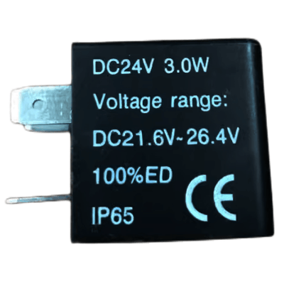
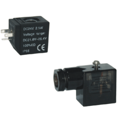
Add) Refer to P362 for detail of sensor switch.
Stroke
| Bore size (mm) | Standard stroke (mm) | Max. std stroke | Max. stroke |
|---|---|---|---|
| 32 | 25 50 75 80 100 125 150 160 175 200 250 300 350 400 450 500 | 1000 | 2000 |
| 40 | 25 50 75 80 100 125 150 160 175 200 250 300 350 400 450 500 600 700 800 900 1000 | 1200 | 2000 |
| 50 | 25 50 75 80 100 125 150 160 175 200 250 300 350 400 450 500 600 700 800 900 1000 | 1200 | 2000 |
| 63 | 25 50 75 80 100 125 150 160 175 200 250 300 350 400 450 500 600 700 800 900 1000 | 1500 | 2000 |
| 80 | 25 50 75 80 100 125 150 160 175 200 250 300 350 400 450 500 600 700 800 900 1000 | 1500 | 2000 |
| 100 | 25 50 75 80 100 125 150 160 175 200 250 300 350 400 450 500 600 700 800 900 1000 | 1500 | 2000 |
[Note] If the stroke is ≥1600mm within the maximum stroke scope, it is treated as non-standard one.
Please contact the company for other special strokes.
Ordering code explanation
| ① Model | ② Bore size | ③ Stroke | ④ Adjustable stroke | ⑤ Magnet | ⑥ Mounting type [Note1] | ⑦ Seals Material | ⑧ Thread type |
|---|---|---|---|---|---|---|---|
| SC: Double acting type | 32 40 50 63 80 100 |
Refer to stroke table for details | No this code | Blank: Without magnet S: With magnet |
Blank LB FA FB CA CB TC |
Blank: TPU H: Viton N: NBR |
Blank: PT G: G |
| SCD: Double rod type | Blank LB FA TC |
||||||
| SCJ: Adjustable stroke type | 10 20 30 40 50 75 100 |
Blank LB FA TC |
[Note1] The accessories are the same as SAU series, please refer to page 41~44 for details;
TC is used with TCM1 and can't be ordered by separately, it must be ordered together with the cylinder.
Inner structure and material of major parts

| NO. | Item | Material |
|---|---|---|
| 1 | Rod nut | Carbon steel |
| 2 | Piston rod | Carbon steel with 20um chrome plated |
| 3 | Front cover packing | TPU |
| 4 | Bushing | Wear resistant material |
| 5 | Front cover | Aluminum alloy |
| 6 | Cushing O-ring | NBR |
| 7 | Cushion gasket | TPU |
| 8 | Barrel | Aluminum alloy |
| 9 | Piston | Aluminum alloy |
| 10 | Piston rod O-ring | NBR |
| 11 | Piston seal | NBR |
| 12 | Magnet | Plastic |
| 13 | Wear ring | Wear resistant material |
| 14 | Bolt | Carbon steel |
| 15 | Back cover | Aluminum alloy |
| 16 | Tie-rod | Carbon steel |
| 17 | Tie-rod nut | Carbon steel |
Note: inner structure & material data sheet is based on certain bore size. Please contact AirTAC if you need inner structure & material data sheet for specific bore size.
Dimensions

| Bore size\Item | A | AB | AC | AD | AE | B | D | DA | E | EA | F | FA | H | K | KA | KB | M | MA | P | PA | PB |
|---|---|---|---|---|---|---|---|---|---|---|---|---|---|---|---|---|---|---|---|---|---|
| 32 | 140 | 47 | 93 | 27.5 | 27.5 | 45 | 12 | 32 | M10×1.25 | 22 | 17 | 6 | 10 | M6×1.0 | 14.5 | 33 | 28 | 15 | 1/8" | 14 | 5.5 |
| 40 | 142 | 49 | 93 | 27.5 | 27.5 | 50 | 16 | 34 | M12×1.25 | 24 | 17 | 7 | 13 | M6×1.0 | 14.5 | 37 | 32 | 15 | 1/4" | 15 | 6 |
| 50 | 150 | 57 | 93 | 27.5 | 27.5 | 62 | 20 | 42 | M16×1.5 | 32 | 23 | 8 | 17 | M6×1.0 | 14.5 | 47 | 38 | 15 | 1/4" | 17 | 8.5 |
| 63 | 153 | 57 | 96 | 27.5 | 27.5 | 75 | 20 | 42 | M16×1.5 | 32 | 23 | 8 | 17 | M8×1.25 | 14.5 | 56 | 38 | 15 | 3/8" | 15 | 9.5 |
| 80 | 182 | 75 | 107 | 33 | 33 | 94 | 25 | 54 | M20×1.5 | 40 | 26 | 10 | 22 | M10×1.5 | 17 | 70 | 47 | 21 | 3/8" | 19.5 | 10 |
| 100 | 188 | 75 | 113 | 33 | 33 | 112 | 25 | 54 | M20×1.5 | 40 | 26 | 10 | 22 | M10×1.5 | 17 | 84 | 47 | 21 | 1/2" | 16.5 | 11 |
Remark: The dimensions of magnet type cylinder are the same as non-magnet type cylinder.
SCD & SCJ Dimensions
| Bore size\Item | A(SCD) | A(SCJ) | AB | AC | DA | DB | E | FA |
|---|---|---|---|---|---|---|---|---|
| 32 | 187 | 182 | 47 | 93 | 32 | 27 | M10X1.25 | 6 |
| 40 | 191 | 185 | 49 | 93 | 34 | 28 | M12X1.25 | 7 |
| 50 | 207 | 194 | 57 | 93 | 42 | 29 | M16X1.5 | 8 |
| 63 | 210 | 197 | 57 | 96 | 42 | 29 | M16X1.5 | 8 |
| 80 | 257 | 238.5 | 75 | 107 | 54 | 35.5 | M20X1.5 | 10 |
| 100 | 263 | 244.5 | 75 | 113 | 54 | 35.5 | M20X1.5 | 10 |
Remark:
1. The dimensions of magnet type cylinder are the same as non-magnet type cylinder.
2. The unmarked dimension is the same as SC standard type.
Series--Big bore size type
Symbol
SC SCD SCJ SC-S SCD-S SCJ-S
Product feature
- ISO6430 standard cylinder.
- The seal of piston adopts heterogeneous two way seal structure. It's dimension is tight and it has the function of grease reservation.
- It is tie rod cylinder. The cylinder barrel and front/rear cap is jointed by tie rods with high reliability.
- Compared with ISO15552 standard cylinder, SC series cylinder with the same bore size is shorter.
- The buffer adjustment of cylinder is smooth and steady.
- Cylinders and mounting accessories with several specifications are optional.
- The seal material with high temperature resistance is adopted, operating temperature range is 0~150°C.
Specification
| Bore size(mm) | 125 | 160 | 200 | 250 |
|---|---|---|---|---|
| Acting type | Double acting | |||
| Fluid | Air(to be filtered by 40um filter element) | |||
| Mounting type | SC: Basic FA FB CA CB LB TC TCM1 | SC: Basic FA FB CA CB LB TC TCM1 | SC: Basic FA FB CA CB LB TC TCM1 | SC: Basic FA FB CA CB LB TC TCM1 |
| SCD, SCJ: Basic FA LB TC TCM1 | SCD, SCJ: Basic FA LB TC TCM1 | SCD, SCJ: Basic FA LB TC TCM1 | SCD, SCJ: Basic FA LB TC TCM1 | |
| Operating pressure | 0.15~1.0MPa(22~145psi)(1.5~10.0bar) | |||
| Proof pressure | 1.5MPa(215psi)(15bar) | |||
| Temperature ℃ | -20~70 | |||
| Speed range mm/s | 30~500 | |||
| Stroke tolerance | 0~250 [+1.0] 251~1000 [+1.5] 1001~1500 [+2.0] | |||
| Cushion type | Variable cushion | |||
| Adjustable cushion stroke | 28 | 29 | 33 | 40 |
| Port size [Note1] | 1/2" | 3/4" | 3/4" | 1" |
[Note1] PT thread, G thread are available.
Add) Refer to P362 for detail of sensor switch.
Stroke
| Bore size (mm) | Standard stroke(mm) | Max. std stroke | Max. stroke |
|---|---|---|---|
| 125 | 25 50 75 80 100 125 150 160 175 200 250 300 350 400 450 500 600 700 800 900 1000 | 1500 | 2000 |
| 160 | 25 50 75 80 100 125 150 160 175 200 250 300 350 400 450 500 600 700 800 900 1000 | 1500 | 2000 |
| 200 | 25 50 75 80 100 125 150 160 175 200 250 300 350 400 450 500 600 700 800 900 1000 | 1500 | 2000 |
| 250 | 25 50 75 80 100 125 150 160 175 200 250 300 350 400 450 500 600 700 800 900 1000 | 1500 | 2000 |
[Note] Please contact the company for other special strokes.
Ordering code

| ① Model | ② Bore size | ③ Stroke | ④ Adjustable stroke | ⑤ Magnet | ⑥ Mounting type [Note1] | ⑦ Seals Material | ⑧ Thread type |
|---|---|---|---|---|---|---|---|
| SC: Double acting type | 125 160 200 250 |
Refer to stroke table for details | No this code | Blank: Without magnet S: With magnet |
Blank LB FA FB CA CB TC |
Blank: NBR H: Viton |
Blank: PT G: G |
| SCD: Double rod type SCJ: Adjustable stroke type |
Blank LB FA TC |
||||||
| 10 20 30 40 50 75 100 |
[Note1] Please refer to page 41~44 for accessory parts. TC is used with TCM1.
Inner structure and material of major parts

| NO. | Item | Material |
|---|---|---|
| 1 | Rod nut | Carbon steel |
| 2 | Piston rod | Carbon steel with 20um chrome plated |
| 3 | Front cover packing | TPU |
| 4 | Bushing | Wear resistant material |
| 5 | Front cover | Aluminum alloy |
| 6 | Cushing O-ring | TPU |
| 7 | O-ring | NBR |
| 8 | Barrel | Aluminum alloy |
| 9 | Piston | Aluminum alloy |
| 10 | Piston rod O-ring | NBR |
| 11 | Piston seal | NBR |
| 12 | Magnet | Plastic |
| 13 | Wear ring | Wear resistant material |
| 14 | Bolt | Carbon steel |
| 15 | Back cover | Aluminum alloy |
| 16 | Tie-rod | Carbon steel |
| 17 | Tie-rod nut | Carbon steel |
Note: inner structure & material data sheet is based on certain bore size. Please contact AirTAC if you need inner structure & material data sheet for specific bore size.
Dimensions

| Bore size\Item | A | AB | AC | AD | AE | B | D | DA | E | EA | F | FA | H | K | KA | KB | M | MA | P | PA | PB |
|---|---|---|---|---|---|---|---|---|---|---|---|---|---|---|---|---|---|---|---|---|---|
| 125 | 203 | 88 | 115 | 38 | 38 | 136 | 32 | 68 | M27×2.0 | 54 | 41 | 13.5 | 27 | M12×1.75 | 21.5 | 104 | 52 | 20 | 1/2" | 20 | 14 |
| 160 | 239 | 113 | 126 | 38 | 38 | 174 | 40 | 88 | M36×2.0 | 72 | 55 | 18 | 36 | M16×2.0 | 21 | 134 | 62 | 25 | 3/4" | 20 | 15 |
| 200 | 244 | 118 | 126 | 38 | 38 | 214 | 40 | 88 | M36×2.0 | 72 | 55 | 18 | 36 | M16×2.0 | 21 | 163 | 62 | 30 | 3/4" | 20 | 15 |
| 250 | 294 | 141 | 153 | 48 | 48 | 267 | 50 | 106 | M42×2.0 | 84 | 65 | 21 | 46 | M20×2.5 | 26.5 | 202 | 86 | 35 | 1" | 25.5 | 22 |
Remark: The dimensions of magnet type cylinder are the same as non-magnet type cylinder.
SCD & SCJ Dimensions (Big bore)
| Bore size\Item | A(SCD) | A(SCJ) | AB | AC | DA | DB | E | FA |
|---|---|---|---|---|---|---|---|---|
| 125 | 291 | 265.5 | 88 | 115 | 68 | 42.5 | M27X2.0 | 13.5 |
| 160 | 352 | 332 | 113 | 126 | 88 | 68 | M36X2.0 | 18 |
| 200 | 362 | 342 | 118 | 126 | 88 | 68 | M36X2.0 | 18 |
| 250 | 435 | 409 | 141 | 153 | 106 | 80 | M42X2.0 | 21 |
Remark:
1. The dimensions of magnet type cylinder are the same as non-magnet type cylinder.
2. The unmarked dimension is the same as SC standard type.
Symbol SCT SCT-S
Product feature
- Standard cylinder manufactured by our enterprise.
- The seal of piston adopts heterogeneous two way seal structure. It's dimension is tight and it has the function of grease reservation.
- It is tie rod cylinder. The cylinder barrel and front/rear cap is jointed by tie rods with high reliability.
- Piston rod can be positioned in several positions in the whole action process.
- The buffer adjustment of cylinder is smooth and steady.
- Cylinders and mounting accessories with several specifications are optional.
- The seal material with high temperature resistance is adopted, operating temperature range is 0~150°C.

Specification
| Bore size(mm) | 32 | 40 | 50 | 63 | 80 | 100 | |
|---|---|---|---|---|---|---|---|
| Acting type | Double acting | ||||||
| Fluid | Air(to be filtered by 40um filter element) | ||||||
| Mounting type | Basic FA FB CA CB LB TC TCM1 | ||||||
| Operating pressure | 0.15~1.0MPa(22~145psi)(1.5~10.0bar) | ||||||
| Proof pressure | 1.5MPa(215psi)(15bar) | ||||||
| Temperature ℃ | -20~70 | ||||||
| Speed range mm/s | 30~800 | ||||||
| Stroke tolerance | 0~250 [+1.0] 251~1000 [+1.5] 1001~1500 [+2.0] | ||||||
| Cushion type | Variable cushion | ||||||
| Adjustable cushion stroke | 21 | 21 | 21 | 21 | 28 | 29 | |
| Port size [Note1] | 1/8" | 1/4" | 1/4" | 3/8" | 3/8" | 1/2" | |
[Note1] PT thread, G thread are available.
Add) Refer to P362 for detail of sensor switch.
Stroke
| Bore size (mm) | Standard stroke(mm) | Max. std stroke | Max. stroke |
|---|---|---|---|
| 32 | 25 50 75 80 100 125 150 160 175 200 250 300 350 400 450 500 | 500 | 800 |
| 40 | 25 50 75 80 100 125 150 160 175 200 250 300 350 400 450 500 | 500 | 800 |
| 50 | 25 50 75 80 100 125 150 160 175 200 250 300 350 400 450 500 | 500 | 800 |
| 63 | 25 50 75 80 100 125 150 160 175 200 250 300 350 400 450 500 | 500 | 800 |
| 80 | 25 50 75 80 100 125 150 160 175 200 250 300 350 400 450 500 | 500 | 800 |
| 100 | 25 50 75 80 100 125 150 160 175 200 250 300 350 400 450 500 | 500 | 800 |
[Note] If the stroke is ≥800mm within the maximum stroke scope, it is treated as non-standard one.
Please contact the company for other special strokes.
Ordering code

| ① Model | ② Bore size | ③ Stroke 1 | ④ Stroke 2 | ⑤ Magnet | ⑥ Mounting type [Note1] | ⑦ Seals Material | ⑧ Thread type |
|---|---|---|---|---|---|---|---|
| SCT: Double acting Multi-position type | 32 40 50 63 80 100 |
Refer to stroke table for details | Refer to stroke table for details | Blank: Without magnet S: With magnet |
Blank LB FA FB CA CB |
Blank: TPU H: Viton N: NBR |
Blank: PT G: G |
[Note1] Please refer to page 41~44 for accessory parts. TC is used with TCM1.
Inner structure and material of major parts

| NO. | Item | Material | NO. | Item | Material |
|---|---|---|---|---|---|
| 1 | Rod nut | Carbon steel | 11 | Magnet | Plastic |
| 2 | Piston rod | Carbon steel with 20um chrome plated | 12 | Gasket | NBR |
| 3 | Packing | TPU | 13 | O-ring | NBR |
| 4 | Bushing | Wear resistant material | 14 | Joint seat | Aluminum alloy |
| 5 | Front cover | Aluminum alloy | 15 | Silencer | |
| 6 | Cushing O-ring | TPU | 16 | Piston | Aluminum alloy |
| 7 | Barrel | Aluminum alloy | 17 | Bolt | Carbon steel |
| Rod O-ring | NBR | 18 | Back cover | Aluminum alloy | |
| 9 | Piston seal | NBR | 19 | Tie-rod | Carbon steel |
| 10 | Wear ring | Wear resistant material | 20 | Tie-rod nut | Carbon steel |
Note: inner structure & material data sheet is based on certain bore size. Please contact AirTAC if you need inner structure & material data sheet for specific bore size.
Dimensions

| Bore size\Item | A | AB | AC | AD | AE | AF | AG | B | D | DA | E | EA | F | FA | H | K | KA | KB | M | MA | P | PA | PB |
|---|---|---|---|---|---|---|---|---|---|---|---|---|---|---|---|---|---|---|---|---|---|---|---|
| 32 | 233 | 47 | 186 | 27.5 | 27.5 | 55 | 38 | 45 | 12 | 32 | M10×1.25 | 22 | 17 | 6 | 10 | M6×1.0 | 14.5 | 33 | 28 | 15 | 1/8" | 14 | 5.5 |
| 40 | 235 | 49 | 186 | 27.5 | 27.5 | 55 | 38 | 50 | 16 | 34 | M12×1.25 | 24 | 17 | 7 | 13 | M6×1.0 | 14.5 | 37 | 32 | 15 | 1/4" | 15 | 6 |
| 50 | 243 | 57 | 186 | 27.5 | 27.5 | 55 | 38 | 62 | 20 | 42 | M16×1.5 | 32 | 23 | 8 | 17 | M6×1.0 | 14.5 | 47 | 38 | 15 | 1/4" | 17 | 8.5 |
| 63 | 249 | 57 | 192 | 27.5 | 27.5 | 55 | 41 | 75 | 20 | 42 | M16×1.5 | 32 | 23 | 8 | 17 | M8×1.25 | 14.5 | 56 | 38 | 15 | 3/8" | 15 | 9.5 |
| 80 | 296 | 75 | 221 | 33 | 33 | 73 | 41 | 94 | 25 | 54 | M20×1.5 | 40 | 26 | 10 | 22 | M10×1.5 | 17 | 70 | 47 | 21 | 3/8" | 19.5 | 10 |
| 100 | 308 | 75 | 233 | 33 | 33 | 73 | 47 | 112 | 25 | 54 | M20×1.5 | 40 | 26 | 10 | 22 | M10×1.5 | 17 | 84 | 47 | 21 | 1/2" | 16.5 | 11 |
Remark: The dimensions of magnet type cylinder are the same as non-magnet type cylinder.
SC Series——Accessories
List for ordering code of accessories
Mounting accessories
| Accessories | LB | FA/FB | CA | CB | TC | TCM1 |
|---|---|---|---|---|---|---|
| Bore size | ||||||
| 32 | F-SC32LB | F-SC32FA | F-SC32CA | F-SC32CB | F-SC32TC | F-SI40TCM1 |
| 40 | F-SC40LB | F-SC40FA | F-SC40CA | F-SC40CB | F-SC40TC | F-SC40TCM1 |
| 50 | F-SC50LB | F-SC50FA | F-SC50CA | F-SC50CB | F-SC50TC | F-SC40TCM1 |
| 63 | F-SC63LB | F-SC63FA | F-SC63CA | F-SC63CB | F-SC63TC | F-SC40TCM1 |
| 80 | F-SC80LB | F-SC80FA | F-SC80CA | F-SC80CB | F-SC80TC | F-SC80TCM1 |
| 100 | F-SC100LB | F-SC100FA | F-SC100CA | F-SC100CB | F-SC100TC | F-SC80TCM1 |
| 125 | F-SC125LB | F-SC125FA | F-SC125CA | F-SC125CB | F-SC125TC | F-SC125TCM1 |
| 160 | F-SC160LB | F-SC160FA | F-SC160CA | F-SC160CB | F-SC160TC | F-SC160TCM1 |
| 200 | F-SC200LB | F-SC200FA | F-SC200CA | F-SC200CB | F-SC200TC | F-SC160TCM1 |
| 250 | F-SC250LB | F-SC250FA | F-SC250CA | F-SC250CB | F-SC250TC | F-SC250TCM1 |
Knuckle & Sensor switches
| Accessories | I: I Knuckle | Y: Y Knuckle | F: F Knuckle | U: U Knuckle | Sensor switch CMSG | Sensor switch DMSG | Sensor switch EMSG |
|---|---|---|---|---|---|---|---|
| Bore size | |||||||
| 32 | F-M10X125I | F-M10X125Y | F-M10X125F | F-M10X125U | CMSG | DMSG | EMSG |
| 40 | F-M12X125I | F-M12X125Y | F-M12X125F | F-M12X125U | CMSG | DMSG | EMSG |
| 50 | F-M16X150I | F-M16X150Y | F-M16X150F | F-M16X150U | CMSG | DMSG | EMSG |
| 63 | F-M16X150I | F-M16X150Y | F-M16X150F | F-M16X150U | CMSG | DMSG | EMSG |
| 80 | F-M20X150I | F-M20X150Y | F-M20X150F | F-M20X150U | CMSG | DMSG | EMSG |
| 100 | F-M20X150I | F-M20X150Y | F-M20X150F | F-M20X150U | CMSG | DMSG | EMSG |
| 125 | F-M27X200I | F-M27X200Y | F-M27X200F | F-M27X200U | CMSG | DMSG | EMSG |
| 160 | F-M36X200I | F-M36X200Y | F-M36X200F | F-M36X200U | CMSG | DMSG | EMSG |
| 200 | F-M36X200I | F-M36X200Y | F-M36X200F | F-M36X200U | CMSG | DMSG | EMSG |
| 250 | F-M42X200Y | F-M42X200Y | - | - | CMSG | DMSG | EMSG |
Accessory selection
| Cylinder model | Cylinder model | LB | FA | FB | CA | CB | TC | TCM1 | I | Y | U | F | CMSG | DMSG | EMSG |
|---|---|---|---|---|---|---|---|---|---|---|---|---|---|---|---|
| SC | Standard | ● | ● | ● | ● | ● | ● | × | × | ||||||
| SC | With magnet | ● | ● | ● | ● | ● | ● | ● | ● | ● | ● | ● | ● | ||
| SCD | Standard | ● | ● | × | × | ● | ● | ● | ● | ● | × | × | × | ||
| SCD | With magnet | ● | ● | × | × | ● | ● | ● | ● | ● | ● | ● | ● | ||
| SCJ | Standard | ● | ● | × | × | ● | ● | ● | ● | ● | ● | × | × | × | |
| SCJ | With magnet | ● | × | × | ● | ● | ● | ● | ● | ● | ● | ||||
| SCT | Standard | ● | ● | ● | ● | × | × | ● | ● | × | × | × | |||
| SCT | With magnet | ● | ● | ● | ● | × | × | ● | ● | ● | ● | ● | ● |
[Note1] Please refer to P358~361 for knuckle detail.
Material of accessories
| Accessories | LB | FA | FB | CA | CB | TC | TCM1 | I | Y | F | U |
|---|---|---|---|---|---|---|---|---|---|---|---|
| Bore size | |||||||||||
| 32~100 | 口 | ● | ◇ | ◇ | ◇ | ◇ | 口 | 口 | 口 | 口 | |
| 125~200 | ◇ | ◇ | ◇ | ◇ | ◇ | ◇ | ◇ | 口 | 口 | 一 | 口 |
| 250 | ◇ | ■ | ■ | ◇ | ◇ | ◇ | ◇ | ■ | ■ |
●—Aluminum alloy, ■—Cast steel, ◇—Nodular cast iron, □—Carbon steel.
Standard cylinder(Tie-rod)
SC Series————Accessories
Dimensions

| Bore size\Item | A | C | AA | AC | AD | AE | AF | AG | AH | AP | AT |
|---|---|---|---|---|---|---|---|---|---|---|---|
| 32 | 140 | 93 | 153 | 134 | 9.5 | 50 | 33 | 20.5 | 28 | 9 | 3 |
| 40 | 142 | 93 | 169 | 140 | 14.5 | 57 | 36 | 23.5 | 30 | 12 | 3 |
| 50 | 150 | 93 | 173 | 149 | 12 | 68 | 47 | 28 | 36.5 | 12 | 3 |
| 63 | 153 | 96 | 184 | 158 | 13 | 80 | 56 | 31 | 41 | 12 | 3 |
| 80 | 182 | 107 | 199 | 167 | 16 | 97 | 70 | 30 | 49 | 14 | 4 |
| 100 | 188 | 113 | 209 | 173 | 18 | 112 | 84 | 30 | 57 | 14 | 4 |
| 125 | 203 | 115 | 221 | 185 | 18 | 136 | 104 | 35 | 70 | 17 | 6 |
| 160 | 239 | 126 | 246 | 206 | 20 | 174 | 134 | 40 | 91 | 17 | 8 |
| 200 | 244 | 126 | 276 | 226 | 25 | 214 | 163 | 50 | 113.5 | 22 | 9 |
| 250 | 294 | 153 | 323 | 273 | 25 | 267 | 201 | 60 | 141 | 26 | 15 |
| Bore size\Item | A | C | DC | DD | DE | DJ | DQ | S | T |
|---|---|---|---|---|---|---|---|---|---|
| 32 | 140 | 93 | 34 | 44.5 | 12 | 9 | 16 | 45 | 33 |
| 40 | 142 | 93 | 34 | 45.5 | 14 | 9 | 20 | 49 | 37 |
| 50 | 150 | 93 | 34 | 46 | 14 | 10 | 20 | 61 | 47 |
| 63 | 153 | 96 | 34 | 46.5 | 14 | 10 | 20 | 74 | 56 |
| 80 | 182 | 107 | 48 | 64.5 | 20 | 14 | 32 | 93 | 70 |
| 100 | 188 | 113 | 48 | 65 | 20 | 14 | 32 | 111 | 84 |
| 125 | 203 | 115 | 32 | 52 | 20 | 17 | 31.7 | 135 | 104 |
| 160 | 239 | 126 | 40 | 68 | 28 | 19.5 | 39.7 | 173 | 134 |
| 200 | 244 | 126 | 60 | 90 | 28 | 23 | 39.7 | 213 | 163 |
| 250 | 294 | 153 | 70 | 106 | 36 | 24 | 49.7 | 255 | 202 |
TC & TCM1 Dimensions

| Bore size\Item | A | C | EB | ED | EE | EP | ET | I | S |
|---|---|---|---|---|---|---|---|---|---|
| 32 | 140 | 93 | 87 | 33 | 55 | 16 | 22 | 17 | 45 |
| 40 | 142 | 93 | 113 | 37 | 63 | 25 | 28 | 17 | 50 |
| 50 | 150 | 93 | 126 | 47 | 76 | 25 | 28 | 23 | 62 |
| 63 | 153 | 96 | 138 | 56 | 88 | 25 | 30 | 23 | 75 |
| 80 | 182 | 107 | 164 | 70 | 114 | 25 | 32 | 26 | 94 |
| 100 | 188 | 113 | 182 | 84 | 132 | 25 | 38 | 26 | 112 |
| 125 | 203 | 115 | 208 | 104 | 158 | 25 | 40 | 41 | 136 |
| 160 | 239 | 126 | 272 | 134 | 200 | 36 | 46 | 55 | 174 |
| 200 | 244 | 126 | 318 | 163 | 246 | 36 | 46 | 55 | 214 |
| 250 | 294 | 153 | 394 | 202 | 304 | 45 | 56 | 65 | 267 |
| Bore size\Item | A | C | HA | HB | HE | HF | HP | HQ | HR | HT | HJ |
|---|---|---|---|---|---|---|---|---|---|---|---|
| 32 | 140 | 93 | 100 | 75 | 90 | 71 | 12 | 16 | 87 | 11 | 54 |
| 40 | 142 | 93 | 103 | 80 | 109 | 86 | 11 | 23 | 113 | 12 | 50 |
| 50 | 150 | 93 | 103 | 80 | 122 | 99 | 11 | 23 | 126 | 12 | 50 |
| 63 | 153 | 96 | 103 | 80 | 134 | 111 | 11 | 23 | 138 | 12 | 50 |
| 80 | 182 | 107 | 110 | 85 | 160 | 137 | 13 | 23 | 164 | 12 | 70 |
| 100 | 188 | 113 | 110 | 85 | 178 | 155 | 13 | 23 | 182 | 12 | 70 |
| 125 | 203 | 115 | 145 | 105 | 211 | 183 | 18 | 25 | 208 | 20 | 85 |
| 160 | 239 | 126 | 185 | 140 | 272 | 236 | 22 | 36 | 272 | 25 | 130 |
| 200 | 244 | 126 | 185 | 140 | 318 | 282 | 22 | 36 | 318 | 25 | 130 |
| 250 | 294 | 153 | 215 | 165 | 394 | 349 | 26 | 45 | 394 | 28 | 160 |
[Note] The installation position of the accessories can not be adjusted arbitrarily.