Compendium of SAI Series
ISO15552 Standard Cylinder Product Catalog
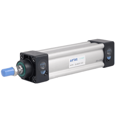
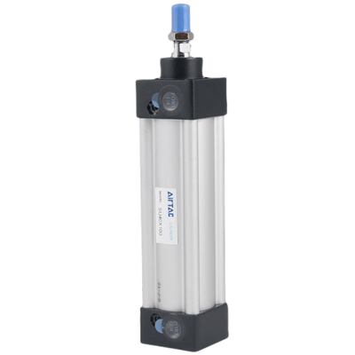
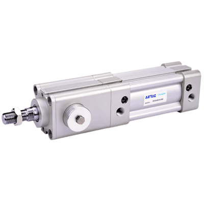
ISO15552 Standard cylinder
Adjustable air buffer With adjustable air buffer on the front and back cover
Bore size: 32,40,50,63,80,100,125,160,200S
Extruded body with switch groove With switch groove on the two sides of body, Four kinds of cylinder joints the counterpart sensor switch type is: CMSE\DMSE.
Multi-mounting accessories: Knuckle, Y Knuckle, Floating Joint, Universal Joint
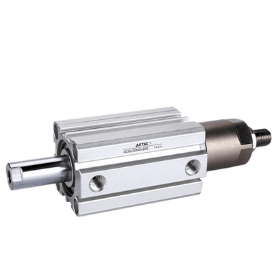
Multi-type cylinder: SAI: Double acting type, SAID: Double rod type, SAIJ: Adjustable stroke type, SAIL: Double acting with locker type, SAIF: With valve type
Criteria for selection: Cylinder thrust
| Bore size | Acting type | Pressure area(mm²) | Operating pressure(MPa) | |||||||||||
|---|---|---|---|---|---|---|---|---|---|---|---|---|---|---|
| Bore size | Rod size | Acting type | 0.1 | 0.2 | 0.3 | 0.4 | 0.5 | 0.6 | 0.7 | 0.8 | 0.9 | 1.0 | ||
| 32 | 12 | Double acting | Push side | 804 | 80.4 | 160.8 | 241.2 | 321.6 | 402.0 | 482.4 | 562.8 | 643.2 | 723.6 | 804.0 |
| 32 | 12 | Double acting | Pull side | 690 | 69.0 | 138.0 | 207.0 | 276.0 | 345.0 | 414.0 | 483.0 | 552.0 | 621.0 | 690.0 |
| 40 | 16 | Double acting | Push side | 1256 | 125.6 | 251.2 | 376.8 | 502.4 | 628.0 | 753.6 | 879.2 | 1004.8 | 1130.4 | 1256.0 |
| 40 | 16 | Double acting | Pull side | 1055 | 105.5 | 211.0 | 316.5 | 422.0 | 527.5 | 633.0 | 738.5 | 844.0 | 949.5 | 1055.0 |
| 50 | 20 | Double acting | Push side | 1963 | 196.3 | 392.6 | 588.9 | 785.2 | 981.5 | 1177.8 | 1374.1 | 1570.4 | 1766.7 | 1963.0 |
| 50 | 20 | Double acting | Pull side | 1649 | 164.9 | 329.8 | 494.7 | 659.6 | 824.5 | 989.4 | 1154.3 | 1319.2 | 1484.1 | 1649.0 |
| 63 | 20 | Double acting | Push side | 3117 | 311.7 | 623.4 | 935.1 | 1246.8 | 1558.5 | 1870.2 | 2181.9 | 2493.6 | 2805.3 | 3117.0 |
| 63 | 20 | Double acting | Pull side | 2803 | 280.3 | 560.6 | 840.9 | 1121.2 | 1401.5 | 1681.8 | 1962.1 | 2242.4 | 2522.7 | 2803.0 |
| 80 | 25 | Double acting | Push side | 5026 | 502.6 | 1005.2 | 1507.8 | 2010.4 | 2513.0 | 3015.6 | 3518.2 | 4020.8 | 4523.4 | 5026.0 |
| 80 | 25 | Double acting | Pull side | 4536 | 453.6 | 907.2 | 1360.8 | 1814.4 | 2268.0 | 2721.6 | 3175.2 | 3628.8 | 4082.4 | 4536.0 |
| 100 | 25 | Double acting | Push side | 7853 | 785.3 | 1570.6 | 2355.9 | 3141.2 | 3926.5 | 4711.8 | 5497.1 | 6282.4 | 7067.7 | 7853.0 |
| 100 | 25 | Double acting | Pull side | 7362 | 736.2 | 1472.4 | 2208.6 | 2944.8 | 3681.0 | 4417.2 | 5153.4 | 5889.6 | 6625.8 | 7362.0 |
| 125 | 32 | Double acting | Push side | 12272 | 1227.2 | 2454.4 | 3681.6 | 4908.8 | 6136.0 | 7363.2 | 8590.4 | 9817.6 | 11044.8 | 12272.0 |
| 125 | 32 | Double acting | Pull side | 11468 | 1146.8 | 2293.6 | 3440.4 | 4587.2 | 5734.0 | 6880.8 | 8027.6 | 9174.4 | 10321.2 | 11468.0 |
| 160 | 40 | Double acting | Push side | 20106 | 2010.6 | 4021.2 | 6031.8 | 8042.4 | 10053.0 | 12063.6 | 14074.2 | 16084.8 | 18095.4 | 20106.0 |
| 160 | 40 | Double acting | Pull side | 18849 | 1884.9 | 3769.8 | 5654.7 | 7539.6 | 9424.5 | 11309.4 | 13194.3 | 15079.2 | 16964.1 | 18849.0 |
| 200 | 40 | Double acting | Push side | 31416 | 3141.6 | 6283.2 | 9424.8 | 12566.4 | 15708.0 | 18849.6 | 21991.2 | 25132.8 | 28274.4 | 31416.0 |
| 200 | 40 | Double acting | Pull side | 30157 | 3015.7 | 6031.4 | 9047.1 | 12062.8 | 15078.5 | 18094.2 | 21109.9 | 24125.6 | 27141.3 | 30157.0 |
Installation and application
- When load changes in the work, the cylinder with abundant output capacity shall be selected.
- Relative cylinder with high temperature resistance or corrosion resistance shall be chosen under the condition of high temperature or corrosion.
- Necessary protection measure shall be taken in the environment with higher humidity, much dust or water drops, oil dust and welding dregs.
- Dirty substances in the pipe must be eliminated before cylinder is connected with pipeline to prevent the entrance of particles into the cylinder.
- The medium used by cylinder shall be filtered to 40um or below.
- Anti-freezing measure shall be adopted under low temperature environment to prevent moisture freezing.
- The cylinder shall be carried out test run without load before application. Prior to run, buffer shall be turned to the minimum and gradually released to avoid the damage on cylinder caused by excessive impact.
- The cylinder shall avoid the influence of side load in operation to maintain the normal work of cylinder and extend the service life.
- If the cylinder is dismantled and stored for a long time, please conduct anti-rust treatment to the surface. Anti-dust caps shall be added in air inlet and outlet ports.
SAI Series Product feature
- 1. ISO15552 (original ISO6431) standard cylinder
- 2. The piston seal adopts heterogeneous two way seal structure, with tight dimension and oil reservation function
- 3. The aluminum profile without tie rod has good corrosion resistance. With sensor switch groove on the two sides of body
- 4. The buffer adjustment of cylinder is smooth and steady
- 5. Cylinders and accessories for installation with several specifications are optional
- 6. The seal material with high temperature resistance is adopted, operating temperature range is 0~150℃
Specification
| Bore size(mm) | 32 | 40 | 50 | 63 | 80 | 100 | 125 | 160 | 200 |
|---|---|---|---|---|---|---|---|---|---|
| Acting type | Double acting | Double acting | Double acting | Double acting | Double acting | Double acting | Double acting | Double acting | Double acting |
| Fluid | Air(to be filtered by 40um filter element) | ||||||||
| Mounting type | SAI | Basic FA FB CA CB CR LB TC FTC TCM1 TCM2 | |||||||
| SAID, SAIJ | Basic FA LB TC FTC TCM1 TCM2 | ||||||||
| Operating pressure | 0.15~1.0MPa(22~145psi)(1.5~10.0bar) | ||||||||
| Proof pressure | 1.5MPa(215psi)(15bar) | ||||||||
| Temperature ℃ | -20~70 | -20~70 | -20~70 | -20~70 | -20~70 | -20~70 | -20~70 | -20~70 | -20~70 |
| Speed range mm/s | 30~800 | 30~800 | 30~800 | 30~800 | 30~800 | 30~500 | 30~500 | 30~500 | 30~500 |
| Stroke tolerance | 0~250+1.0 251~1000+1.5 1001~1500+2.0 | ||||||||
| Cushion type | Variable cushion | ||||||||
| Adjustable cushion stroke | 27 | 27 | 30 | 30 | 36 | 36 | 40 | 50 | 50 |
| Port size[Note1] | 1/8" | 1/4" | 1/4" | 3/8" | 3/8" | 1/2" | 1/2" | 3/4" | 3/4" |
[Note1] PT thread, G thread are available.
Add) Refer to P362 for detail of sensor switch.
Stroke
| Bore size(mm) | Standard stroke (mm) | Max. std stroke | Max. stroke |
|---|---|---|---|
| 32 | 25 50 75 80 100 125 150 160 175 200 250 300 350 400 450 500 | 1000 | 1800 |
| 40 | 25 50 75 80 100 125 150 160 175 200 250 300 350 400 450 500 600 700 800 | 1200 | 1800 |
| 50 | 25 50 75 80 100 125 150 160 175 200 250 300 350 400 450 500 600 700 800 900 1000 | 1200 | 1800 |
| 63 | 25 50 75 80 100 125 150 160 175 200 250 300 350 400 450 500 600 700 800 900 1000 | 1500 | 1800 |
| 80 | 25 50 75 80 100 125 150 160 175 200 250 300 350 400 450 500 600 700 800 900 1000 | 1500 | 1800 |
| 100 | 25 50 75 80 100 125 150 160 175 200 250 300 350 400 450 500 600 700 800 900 1000 | 1500 | 1800 |
| 125 | 25 50 75 80 100 125 150 160 175 200 250 300 350 400 450 500 600 700 800 900 1000 | 1500 | 1800 |
| 160 | 25 50 75 80 100 125 150 160 175 200 250 300 350 400 450 500 600 700 800 900 1000 | 1500 | 2000 |
| 200 | 25 50 75 80 100 125 150 160 175 200 250 300 350 400 450 500 600 700 800 900 1000 | 1500 | 2000 |
[Note] Consult us for non-standard stroke.
Model Coding
SAI 160×50 S□ □
SAID 160×50 S□ □
SAIJ 160×50-20 S□ □ □
| ① Model | ② Bore size | ③ Rod Material | ④ Stroke | ⑤ Adjustable stroke | ⑥ Magnet | ⑦ Mounting type[Note1] | ⑧ Seals Material | ⑨ Thread type |
|---|---|---|---|---|---|---|---|---|
| SAI:Double acting type | 32 40 50 63 80 100 125 160 200 | Blank:Medium carbon steel A: SUS420J2 B: SUS304 |
Refer to stroke table for details | No this code | Blank:Without magnet S: With magnet |
Blank (no special mounting) | Blank:TPU H: Viton N:NBR |
Blank:PT G:G |
| SAI:Double acting type | 32 40 50 63 80 100 125 160 200 | Blank:Medium carbon steel A: SUS420J2 B: SUS304 |
Refer to stroke table for details | No this code | Blank:Without magnet S: With magnet |
LB | Blank:TPU H: Viton N:NBR |
Blank:PT G:G |
| SAI:Double acting type | 32 40 50 63 80 100 125 160 200 | Blank:Medium carbon steel A: SUS420J2 B: SUS304 |
Refer to stroke table for details | No this code | Blank:Without magnet S: With magnet |
FA | Blank:TPU H: Viton N:NBR |
Blank:PT G:G |
| SAI:Double acting type | 32 40 50 63 80 100 125 160 200 | Blank:Medium carbon steel A: SUS420J2 B: SUS304 |
Refer to stroke table for details | No this code | Blank:Without magnet S: With magnet |
FB | Blank:TPU H: Viton N:NBR |
Blank:PT G:G |
[Note1] CR is used with CB; FTC, TC are used with TCM1, TCM2, please refer to page 22~24 for details.
Inner structure and material of major parts

| NO. | Item | Material |
|---|---|---|
| 1 | Rod nut | Carbon steel\Stainless steel |
| 2 | Piston rod | Carbon steel with 20um chrome plated or Stainless steel |
| 3 | Front cover packing | TPU |
| 4 | Front cover | Aluminum alloy |
| 5 | Bushing | Wear resistant material |
| 6 | Cushion O-ring | TPU |
| 7 | Barrel | Aluminum alloy |
| 8 | O-ring | NBR |
| 9 | Piston | Aluminum alloy |
| 10 | Piston Seal | NBR |
| 11 | Wear ring | Wear resistant material |
| 12 | Magnet | Plastic(Ø100 and below)\Rubber(Others) |
| 13 | Bolt | Carbon steel |
| 14 | Buffer gasket | TPU |
| 15 | Back cover | Aluminum alloy |
| 16 | Screw | Carbon steel\Stainless steel |
Dimensions (SAI)

| Bore size item | A | AB | AC | AD | AE | B | D | DA | E | EA | F | FA | M | MA | H | K | KA | KB | N | NA | P | PA | PB |
|---|---|---|---|---|---|---|---|---|---|---|---|---|---|---|---|---|---|---|---|---|---|---|---|
| 32 | 142 | 48 | 94 | 27.5 | 27.5 | 47 | 12 | 29 | M10×1.25 | 22 | 17 | 6 | 30 | 19 | 10 | M6 | 16 | 32.5 | 30 | 3 | 1/8" | 13 | 5.5 |
| 40 | 159 | 54 | 105 | 32 | 32 | 53 | 16 | 33 | M12×1.25 | 24 | 17 | 7 | 35 | 21 | 13 | M6 | 17 | 38 | 35 | 3.5 | 1/4" | 17 | 6 |
| 50 | 175 | 69 | 106 | 31 | 31 | 65 | 20 | 42 | M16×1.5 | 32 | 23 | 8 | 40 | 27 | 17 | M8 | 17 | 46.5 | 40 | 3.5 | 1/4" | 15.5 | 7.5 |
| 63 | 190 | 69 | 121 | 33 | 33 | 75 | 20 | 42 | M16×1.5 | 32 | 23 | 8 | 45 | 27 | 17 | M8 | 17 | 56.5 | 45 | 4 | 3/8" | 16.5 | 7.5 |
| 80 | 214 | 86 | 128 | 33 | 33 | 95 | 25 | 53 | M20×1.5 | 40 | 26 | 10 | 45 | 33 | 22 | M10 | 19 | 72 | 45 | 4 | 3/8" | 16.5 | 9 |
| 100 | 229 | 91 | 138 | 37 | 37 | 115 | 25 | 55 | M20×1.5 | 40 | 26 | 10 | 55 | 36 | 22 | M10 | 19 | 89 | 55 | 4 | 1/2" | 18.5 | 9.5 |
| 125 | 279 | 119 | 160 | 46 | 46 | 140 | 32 | 74 | M27×2.0 | 54 | 41 | 13.5 | 60 | 45 | 27 | M12 | 22 | 110 | 60 | 4 | 1/2" | 23 | 14 |
| 160 | 332 | 152 | 180 | 50 | 50 | 180 | 40 | 94 | M36×2.0 | 72 | 55 | 18 | 65 | 58 | 36 | M16 | 30 | 140 | 65 | 4 | 3/4" | 25 | 15 |
| 200 | 347 | 167 | 180 | 50 | 50 | 220 | 40 | 100 | M36×2.0 | 72 | 55 | 18 | 75 | 67 | 36 | M16 | 30 | 175 | 75 | 5 | 3/4" | 25 | 15 |
Remark: The dimensions of magnet type cylinder are the same as non-magnet type cylinder.
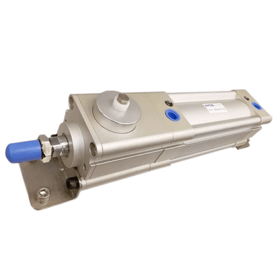
SAIL Series—With locker type
Product feature
- 1. With lock cylinder: front cover with lock type and rear cover lock type
- 2. The way of unlocking: automatic and manual
Specification
| Bore size(mm) | 40 | 50 | 63 | 80 | 100 | 125 | 160 | 200 |
|---|---|---|---|---|---|---|---|---|
| Acting type | Double acting | Double acting | Double acting | Double acting | Double acting | Double acting | Double acting | Double acting |
| Fluid | Air(to be filtered by 40um filter element) | |||||||
| Mounting type | Basic FA FB CA CB CR LB TC FTC TCM1 TCM2 | |||||||
| Operating pressure | 0.15~1.0MPa(22~145psi)(1.5~10.0bar) | |||||||
| Proof pressure | 1.5MPa(215psi)(15bar) | |||||||
| Temperature ℃ | -20~70 | -20~70 | -20~70 | -20~70 | -20~70 | -20~70 | -20~70 | -20~70 |
| Speed range mm/s | 30~800 | 30~800 | 30~800 | 30~800 | 30~800 | 30~500 | 30~500 | 30~500 |
| Stroke tolerance | 0~250+1.0 251~1000+1.5 1001~1500+2.0 | |||||||
| Cushion type | Variable cushion | |||||||
| Adjustable cushion stroke (No locker end) | 27 | 30 | 30 | 36 | 36 | 40 | 50 | 50 |
| Adjustable cushion stroke (With locker end) | 20 | 20 | 21 | 22.5 | 24 | 24 | 28 | 28 |
| Port size[Note1] | 1/4" | 1/4" | 3/8" | 3/8" | 1/2" | 1/2" | 3/4" | 3/4" |
[Note1] PT thread, G thread are available.
Add) Refer to P362 for detail of sensor switch.
Use and maintenance
- Under the condition of locking, there is a great danger to the gas port A when there is no pressure on both sides of the air port. There is a great danger similar to the release of locking, or the sudden release of lock and the piston rod flying. When the locking mechanism is lifted, it is necessary to supply the pressure of the air inlet B and remove the lock mechanism without load.
- If the fast exhaust valve is used to speed down the drop speed, the cylinder noumenon is sometimes started than the lock pin first and can not be removed normally. Therefore, please do not use the fast exhaust valve with the lock cylinder.
- Please do not use three solenoid valves: please do not combine with three (especially the seal type metal seal) solenoid valve. If pressure is sealed in the air inlet with the locking mechanism side, the lock will not work. In addition, even if it is temporarily locked, the air leaked from the solenoid valve will enter the cylinder, and the lock will be lifted after a period of time.
- If the locking mechanism side bears the back pressure, sometimes the lock will be lifted, so please use a single or integrated individual exhaust type solenoid valve.
- If the cylinder with adjustable cushioning is excessive, if the air cushion valve needle on the locking mechanism side is screwed too much, the piston will sometimes cause restraint at the stroke terminal, causing the damage of the locking mechanism. Therefore, the needle valve should be adjusted to make the piston not be restrained.
- When the manual operation of the locking mechanism is completed, it is necessary to reset the manual device to the in situ. In addition, please do not do manual operation outside the adjustment, otherwise it will be more dangerous.
- When the cylinder is installed and adjusted, please dissolve the lock: in the lock state of the installation and other operations, sometimes it causes the lock-in parts to be damaged.
- Please do not use multiple cylinders at the same time: please do not use more than 2 locking cylinders at the same time to drive a workpiece. Sometimes one of the cylinders will not be locked out.
- Please use the speed control valve in the exhaust throttle control state: in the intake throttling control, it is sometimes impossible to release the lock.
- In the lock side, please be sure to use the terminal of the cylinder stroke: if the piston of the cylinder does not reach the terminal, locking will fail or lock.
- Manual operation is a non locking way to release: pull the lever into the anti falling piston, and pull the bolt out of the 4mm with the force of more than 20N. After the piston is moved away, it can release the lock. (no load level installation or opposite side port pressurization), or after loosened, the anti falling piston returns to the original position through the action of the stop spring and enters the piston rod groove, and the piston becomes locked.
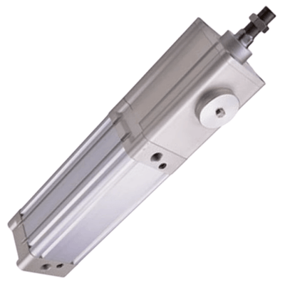
SAIF Series—With valve type
Product feature
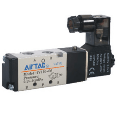
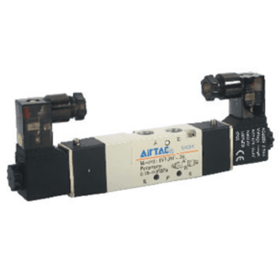
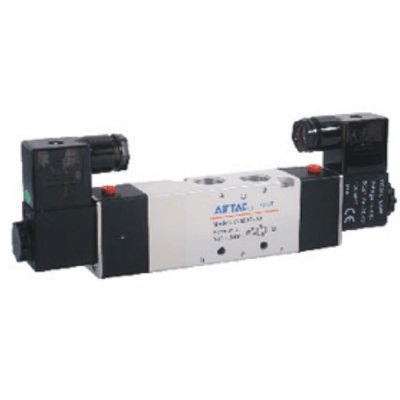
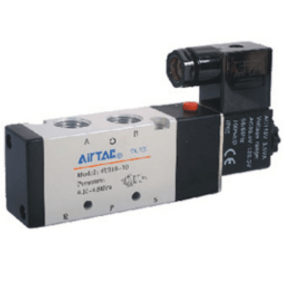
- 1. For Standard Cylinders: use 4M210 valve for bore size 32, 40 & 50; 4M310 valve for bore size 63, 80 & 100mm.
- 2. Individually control, no need for extra solenoid valves.
- 3. Installation time & space saving; suitable for decentralize installation in large system.
- 4. Options of mounting accessories & easy installation.
Specification
| Cylinder specification | 32 | 40 | 50 | 63 | 80 | 100 | |
|---|---|---|---|---|---|---|---|
| Bore size(mm) | 32 | 40 | 50 | 63 | 80 | 100 | |
| Acting type | Double acting | Double acting | Double acting | Double acting | Double acting | Double acting | |
| Fluid | Air(to be filtered by 40um filter element) | ||||||
| Mounting type | Basic FA FB CA CB CR LB TC FTC TCM1 TCM2 | ||||||
| Operating pressure | 0.15~1.0MPa(22~145psi)(1.5~10.0bar) | ||||||
| Proof pressure | 1.5MPa(215psi)(15bar) | ||||||
| Temperature ℃ | -20~70 | -20~70 | -20~70 | -20~70 | -20~70 | -20~70 | |
| Speed range mm/s | 30~800 | 30~800 | 30~800 | 30~800 | 30~800 | 30~800 | |
| Stroke tolerance | 0~250+1.0 251~1000+1.5 1001~1500+2.0 | ||||||
| Cushion type | Variable cushion | ||||||
| Adjustable cushion stroke | 27 | 27 | 30 | 30 | 36 | 36 | |
| Port size | 1/8" | 1/4" | 1/4" | 3/8" | 3/8" | 1/2" | |
| PU tube size(OD×ID) | Ø8×Ø5 | Ø8×Ø5 | Ø8×Ø5 | Ø8×Ø5 | Ø10×Ø6.5 | Ø10×Ø6.5 | |
| Solenoid valve specification | Solenoid valve specification | ||||||
| Model | 4M210-06&4M210-08 | 4M210-06&4M210-08 | 4M210-06&4M210-08 | 4M310-08&4M310-10 | 4M310-08&4M310-10 | 4M310-08&4M310-10 | |
| Fluid | Air(to be filtered by 40um filter element) | ||||||
| Acting type | Internal piloted | ||||||
| Port size [Note 1] | In=Exhaust=1/8"& In=1/4"Exhaust=1/8" | ||||||
| Orifice size | 4M210-06:14.0mm²(Cv=0.78) 4M210-08:16.0mm²(Cv=0.89) |
4M210-06:14.0mm²(Cv=0.78) 4M210-08:16.0mm²(Cv=0.89) |
4M210-06:14.0mm²(Cv=0.78) 4M210-08:16.0mm²(Cv=0.89) |
4M310-08:25.0mm²(Cv=1.40) 4M310-10:30.0mm²(Cv=1.68) |
4M310-08:25.0mm²(Cv=1.40) 4M310-10:30.0mm²(Cv=1.68) |
4M310-08:25.0mm²(Cv=1.40) 4M310-10:30.0mm²(Cv=1.68) |
|
| Valve type | 5 port 2 position | ||||||
| Operating pressure | 0.15~0.8MPa(21~114psi) | ||||||
| Proof pressure | 1.2MPa(175psi) | ||||||
| Temperature ℃ | -20~70 | -20~70 | -20~70 | -20~70 | -20~70 | -20~70 | |
| Body material | Aluminum alloy | ||||||
| Lubrication[Note2] | Not required | ||||||
| Max. frequency[Note3] | 5 cycle/sec | 5 cycle/sec | 5 cycle/sec | 4 cycle/sec | 4 cycle/sec | 4 cycle/sec | |
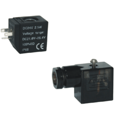
| Coil specification | Coil specification | ||||||
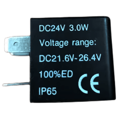
| Standard voltage | AC220V、AC110V、AC24V、DC24V、DC12V | ||||||
| Scope voltage | AC:±15% DC:±10% | ||||||
| Power consumption | AC:3.5VA DC:3.0W | ||||||
| Protection | IP65(DIN40050) | ||||||
| Temperature classification | B Class | ||||||
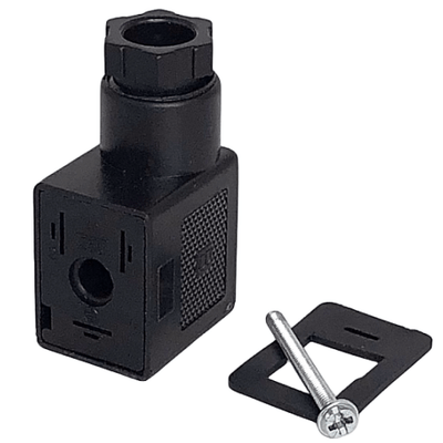
| Electrical entry | Terminal, Grommet | ||||||
| Activating time | Activating time | 0.05 sec and below | 0.05 sec and below | 0.05 sec and below | 0.05 sec and below | 0.05 sec and below | 0.05 sec and below |
[Note1] PT thread, G thread are available.
[Note2] It cann't stop in the midway of lubricating. Lubricants like ISO VG32 or equivalent are recommended.
[Note3] The maximum actuation frequency is in the no-load state.
Add) Refer to P362 for detail of sensor switch.
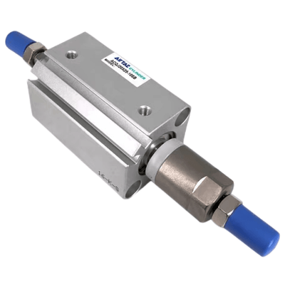
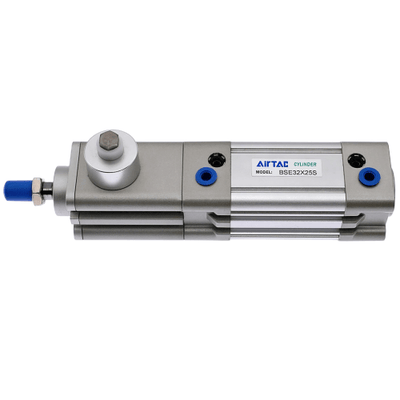
BSAI Series—Enclasp type
Product feature
- Spring and gripper patch enclasp equipment
- Simplicity in structure
- Celerity and availability locked or unlocked
- Bidirectional lock
- State switch steadily
- Spring gripper patch enclasp equipment
- Compact enclasp equipment to save space
- Air pressure unlocked mode and manual unlocked mode are available
- The body is the same as SAI series
- The body is SAI series standard cylinder's body for mounting expediently.
- The mounting accessories(Besides FTC) and the sensor switch are the same as SAI series cylinder.
- Multi-type cylinder and bore size BSAI, BSAID type available
- Bore size: 32, 40, 50, 63, 80, 100, 125
How to mount and use
- The locker equipment only be locked after cylinder stopped, can't brake the piston rod while it is moving. If the lock cylinder be used for control system with safety demand, other safety measure is required.
- The locker equipment only be unlocked when the air pressure on both sides of piston rod are equation or the cylinder stopped, otherwise piston rod movies abruptly might produce accident.
- Typical applications

SAI Series—Accessories
List for ordering code of accessories
| Accessories | Mounting accessories | LB | FA/FB | CA | CB | CR | TC | FTC | TCM1 | TCM2 |
|---|---|---|---|---|---|---|---|---|---|---|
| Bore size | ||||||||||
| 32 | F-SI32LB | F-SI32FA | F-SE32CA | F-SE32CB | F-SI32CR | F-SAI32TC | F-SI32FTC | F-SI32TCM1 | F-SI32TCM2 | |
| 40 | F-SI40LB | F-SI40FA | F-SE40CA | F-SE40CB | F-SI40CR | F-SAI40TC | F-SI40FTC | F-SI40TCM1 | F-SI40TCM2 | |
| 50 | F-SI50LB | F-SI50FA | F-SE50CA | F-SE50CB | F-SI50CR | F-SAI50TC | F-SI50FTC | F-SI40TCM1 | F-SI40TCM2 | |
| 63 | F-SI63LB | F-SI63FA | F-SE63CA | F-SE63CB | F-SI63CR | F-SAI63TC | F-SI63FTC | F-SI63TCM1 | F-SI63TCM2 | |
| 80 | F-SI80LB | F-SI80FA | F-SE80CA | F-SE80CB | F-SI80CR | F-SAI80TC | F-SI80FTC | F-SI63TCM1 | F-SI63TCM2 | |
| 100 | F-SI100LB | F-SI100FA | F-SE100CA | F-SE100CB | F-SI100CR | F-SAI100TC | F-SI100FTC | F-SI125TCM1 | F-SI125TCM2 | |
| 125 | F-SI125LB | F-SI125FA | F-SE125CA | F-SE125CB | F-SI125CR | F-SAI125TC | F-SI125FTC | F-SI125TCM1 | F-SI125TCM2 | |
| 160 | F-SI160LB | F-SI160FA | F-SI160CA | F-SI160CB | F-SI160CR | F-SI160TC | F-SI160FTC | F-SI160TCM1 | F-SI160TCM2 | |
| 200 | F-SI200LB | F-SI200FA | F-SI200CA | F-SI200CB | F-SI200CR | F-SI200TC | F-SI200FTC | F-SI200TCM1 | F-SI160TCM2 |