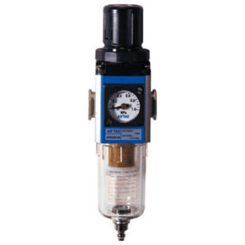
Airtac GFR Filter Regulator GFR300C10MJF1K
The AirTAC Airtac GFR Filter Regulator GFR300C10MJF1K is a genuine G-series filter regulator: water separation, 40 µm particulate filtration and balanced-type pressure regulation combined in a single body. It has See datasheet ports, a differential-pressure drain and regulates 0.15 - 0.9 MPa (20 - 130 psi). It does not lubricate — add a GL lubricator, or order the GFC two-unit set, if downstream equipment needs oil.
- TypeFilter regulator
- Port sizeSee datasheet
- Regulating range0.15 - 0.9 MPa (20 - 130 psi)
- Filtering grade40 µm
- DrainDifferential-pressure drain
- Bowl materialPC
- Pressure gaugeFitted
- ThreadPT
- No minimum order. A single piece can be ordered.
- Ready in 3–5 business days. That is the time we take to process the order and hand it to the carrier. Transit time after that depends on the destination.
About the Airtac GFR Filter Regulator GFR300C10MJF1K
GFR300C10MJF1K is a genuine AirTAC G-series filter regulator: one body doing filtration and pressure regulation, sized 300 with a PT3/8 in port. The K at the end of the code means a reverse (check) valve is fitted, so downstream pressure is held if the upstream supply is lost. This configuration also has a manual drain bowl, the standard 40 um element, no bracket (J code), and an embedded square gauge on MPa scale. Manual drain gives a regulating range of 0.05-0.9 MPa (7-130 psi); the bowl is PC (polycarbonate) at this size.
It is a genuine AirTAC part. The G series covers sizes 200, 300, 400 and 600 with ports from 1/8 in to 1 in, drain types, 40 um or 5 um elements, gauge choices and PT, G or NPT threads. Maximum inlet pressure is 1.0 MPa (145 psi) and the temperature range is -5 to 70 C, non-freezing. Because flow is published as curves rather than a single rated figure, we confirm datasheet figures for your conditions on request.
Airtac GFR Filter Regulator GFR300C10MJF1K Technical Specifications
| Model | Airtac GFR Filter Regulator GFR300C10MJF1K |
|---|---|
| Series | GFR300 filter regulator |
| Port size | See datasheet (PT thread) |
| Filtering grade | 40 µm |
| Regulating range | 0.15 - 0.9 MPa (20 - 130 psi) |
| Pressure type | Standard type |
| Adjusting mechanism | Balanced type |
| Fluid | Compressed air |
|---|---|
| Max. working pressure | 1.0 MPa (145 psi) |
| Temperature range | -5 to +70 °C (unfreeze) |
| Drain type | Differential-pressure drain |
| Bowl material | PC |
| Pressure gauge | Fitted — factory standard, Factory standard scale |
| Reflux valve | Not fitted |
Specifications follow the official AirTAC G-series air-preparation data. The regulating band is set by the drain type: automatic and differential-pressure drains regulate 0.15 - 0.9 MPa, a manual drain regulates 0.05 - 0.9 MPa. Standard type, regulating 0.15 - 0.9 MPa (20 - 130 psi). Air must not freeze in the unit. Flow curves, weight and outline dimensions are not published in our data set — ask us and we will confirm from the factory datasheet.
Model Code: Airtac GFR Filter Regulator GFR300C10MJF1K
| GFR300 | G-series filter regulator, 300 body — sets the port range. |
|---|---|
| C1 | Port size See datasheet. This body offers 08 = PT1/4", 10 = PT3/8", 15 = PT1/2". |
| (blank) | Drain: Differential-pressure drain — this also sets the regulating band (0.15 - 0.9 MPa (20 - 130 psi)). |
| (blank) | Standard type. Blank is standard, L is the low-pressure type. |
| (blank) | Mounting bracket included. |
| (blank) | Pressure gauge fitted (blank). |
| (blank) | Gauge shape: Factory standard. C is round, F is square. |
| (blank) | Gauge scale: Factory standard. 1 is MPa, 2 is psi, 3 is bar. |
| (blank) | Filtering grade 40 µm. Only 40 µm (blank) and 5 µm (W) exist. |
| (blank) | PT thread. PT is the default; G is BSPP and T is NPT. |
| (blank) | No reverse-flow valve (the default). |
Field order is size, port, drain, type, bracket, gauge, shape, scale, grade, thread, reflux — a blank position takes the default. Example: GFR300-08 is a 300 body, PT1/4", differential drain, standard type, bracket included, gauge fitted, 40 µm, PT thread, no reflux valve.
Size Class
- GFR200PT1/8" - PT1/4"
- GFR300PT1/4" - PT1/2"
- GFR400PT3/8" - PT1/2"
- GFR600PT3/4" - PT1"
A larger body carries a larger port and holds set pressure better as flow rises. AirTAC publishes flow only as curves, so size the body from your peak demand with headroom. The GFR600 uses an aluminium-alloy bowl; the 200, 300 and 400 bodies use PC.
| This model | GFR300 · See datasheet · 40 µm |
|---|---|
| One size down | GFR200 |
| One size up | GFR400 |
| Add lubrication | GFC300-C1 (two-unit set) |
Where the Airtac GFR Filter Regulator GFR300C10MJF1K Is Used
Robot gripper manifold
Feeds a robotic end-of-arm gripper circuit where the check valve keeps the grip pressure stable if the plant air supply is interrupted mid-cycle.
Spring-return actuator hold
Supplies a spring-return pneumatic actuator that must stay pressurised against its spring; the reverse valve prevents the set pressure from bleeding back when the upstream valve closes.
Maintenance shop air drop
A dedicated regulated drop at a plant maintenance bay, where the manual-drain bowl is emptied at the end of each shift and the MPa gauge keeps tool pressures consistent.
Is the Airtac GFR Filter Regulator GFR300C10MJF1K the Right Unit?
Choose the 300 size with a 3/8 in port as the mid step of the G range, moving up to 400 or 600 for heavier demand. The K code's built-in check valve matters wherever a sudden supply loss would let a load drop or a setting drift; without that need, the plain MJF1 saves the option. Manual drain gives the full 0.05-0.9 MPa (7-130 psi) span but needs hand draining at intervals. The 40 um element is the standard grade; the 5 um W variant is available for cleaner duties. The square gauge is embedded and MPa-scaled, with psi and bar options, and PT is the standard thread while G and NPT are orderable options. Bracket omitted per the J code. Flow appears only as curves, so ask us to confirm sizing against your application before ordering.
Quick checklist
- ✓ Body size for your peak flow (See datasheet here)
- ✓ Element 40 µm or 5 µm
- ✓ Drain sets the regulating band
- ✓ Gauge fitted, shape and scale
- ✓ Thread PT, G (BSPP) or NPT
- ✓ Oil needed downstream? Use GFC instead
Installation & Maintenance Notes
- check Mount vertically, bowl down, following the airflow arrow.
- check One body does the filtering and the regulating — no separate regulator needed.
- check Keep inlet pressure at or below 1.0 MPa (145 psi).
- check Adjust only within 0.15 - 0.9 MPa (20 - 130 psi).
- check Drain condensate before the bowl fills.
- check Keep the unit above freezing (-5 to +70 °C, unfreeze).
The PC bowl must not be cleaned with solvents — wipe it with a dry cloth. Without the K option, air cannot flow back through the unit. A filter regulator adds no oil to the line.
Airtac GFR Filter Regulator GFR300C10MJF1K FAQ
There is no single rated flow figure for this unit: AirTAC publishes G-series performance as flow curves. Share your working pressure and air demand with us and we will confirm the relevant flow figures from the datasheet on request before you order.
The K code fits a reverse (check) valve in the unit, so regulated downstream pressure is retained if the upstream supply is shut off or lost. If you do not need that hold function, the same regulator without the K code is available as GFR300C10MJF1.
Authorized Export Seller
Genuine AirTAC parts produced by AirTAC factory.
1-Year Warranty
Covers non-human-caused product damage.
Fast Dispatch
Standard models are processed and dispatched in 3-5 business days.
Fast Reply
Most inquiries answered within 7-8 hours.
Request a Quote for Airtac GFR Filter Regulator GFR300C10MJF1K
Send us the quantity, thread type (PT / G / NPT), gauge scale and destination. We confirm price, availability and lead time — usually within 7-8 hours.