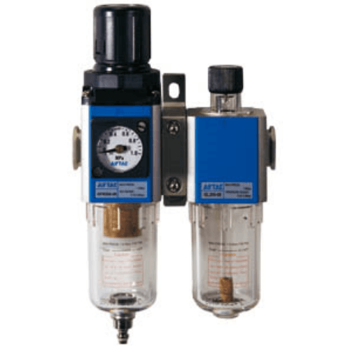
AirTAC GFC400-10 Combination Unit (GFC40010AF1WTK)
The AirTAC GFC400-10 Combination Unit (GFC40010AF1WTK) is a genuine G-series two-unit air-preparation set: a filter regulator that filters and regulates in one body, coupled to a lubricator. Two bodies do the work of three, with PT3/8" ports, a 5 µm element, a automatic drain and regulation over 0.15 - 0.9 MPa (20 - 130 psi).
- TypeTwo-unit set (F.R. + L.)
- Port sizePT3/8"
- Regulating range0.15 - 0.9 MPa (20 - 130 psi)
- Filtering grade5 µm
- DrainAutomatic drain
- Bowl materialPC
- Pressure gaugeFitted
- ThreadNPT
- No minimum order. A single piece can be ordered.
- Shipped from our own warehouse: most standard models dispatch in 3–5 days; custom and non-standard models take 8–10 business days. Transit time after that depends on the destination.
About the AirTAC GFC400-10 Combination Unit (GFC40010AF1WTK)
GFC40010AF1WTK is the check-valve version of AirTAC's two-unit G-series set: a filter-regulator plus a lubricator, filtering water and particulate from the compressed air, regulating downstream pressure and adding oil mist for tools and cylinders. The trailing K codes a reverse (check) valve fitted in the regulator section. This 400-size set takes a NPT3/8 port, has an automatic drain on the filter bowl, a 5 um (W) element, and a square pressure gauge with MPa scale. Maximum working pressure is 1.0 MPa (145 psi); working temperature is -5 to 70 C, non-freezing. The 400-size bowls are polycarbonate.
This is a genuine AirTAC part. The same set is available without the check valve as GFC40010AF1W, and the G-series spans 200, 300, 400 and 600 sizes with 1/8 to 1 inch ports, manual, automatic or differential-pressure drains, 40 um or 5 um elements, round or square gauges in MPa, psi or bar scales, and three thread types (NPT on this code). Flow appears as curves rather than a single rating, so ask us to confirm sizing from the datasheet on request.
AirTAC GFC400-10 Combination Unit (GFC40010AF1WTK) Technical Specifications
| Model | AirTAC GFC400-10 Combination Unit (GFC40010AF1WTK) |
|---|---|
| Series | GFC400 two-unit set |
| Composition | Filter regulator + lubricator (2 units) |
| Port size | PT3/8" (NPT thread) |
| Filtering grade | 5 µm |
| Regulating range | 0.15 - 0.9 MPa (20 - 130 psi) |
| Pressure type | Standard type |
| Fluid | Compressed air |
|---|---|
| Max. working pressure | 1.0 MPa (145 psi) |
| Temperature range | -5 to +70 °C (unfreeze) |
| Drain type | Automatic drain |
| Bowl material | PC |
| Pressure gauge | Fitted — square, MPa scale |
| Reflux valve | Fitted (reverse flow permitted) |
Specifications follow the official AirTAC G-series air-preparation data. The regulating band is set by the drain type: automatic and differential-pressure drains regulate 0.15 - 0.9 MPa, a manual drain regulates 0.05 - 0.9 MPa. Standard type, regulating 0.15 - 0.9 MPa (20 - 130 psi). The set has no separate bracket code — the two units couple together with their own mounting hardware. Flow curves, weight and outline dimensions are not published in our data set — ask us and we will confirm from the factory datasheet.
Model Code: AirTAC GFC400-10 Combination Unit (GFC40010AF1WTK)
| GFC400 | G-series two-unit set, 400 body — sets the port range. |
|---|---|
| 10 | Port size PT3/8". This body offers 10 = PT3/8", 15 = PT1/2". |
| A | Drain: Automatic drain — this also sets the regulating band (0.15 - 0.9 MPa (20 - 130 psi)). |
| (blank) | Standard type. Blank is standard, L is the low-pressure type. |
| (blank) | Pressure gauge fitted (blank). |
| F | Gauge shape: Square. C is round, F is square. |
| 1 | Gauge scale: MPa. 1 is MPa, 2 is psi, 3 is bar. |
| W | Filtering grade 5 µm. Only 40 µm (blank) and 5 µm (W) exist. |
| T | NPT thread. PT is the default; G is BSPP and T is NPT. |
| K | Reverse-flow (reflux) valve fitted. |
Field order is size, port, drain, type, gauge, shape, scale, grade, thread, reflux — there is no bracket position on a combination set. Constituent units, orderable separately as spares: GFR400-10 filter regulator and GL400-10 lubricator.
Size Class & How It Differs From GC
- GFC200PT1/8" - PT1/4"
- GFC300PT1/4" - PT1/2"
- GFC400PT3/8" - PT1/2"
- GFC600PT3/4" - PT1"
A GFC is two units because filtering and regulating share one body. A GC is three separate units — filter, regulator and lubricator. Both filter, regulate and lubricate; the GFC is the shorter assembly, the GC keeps the filter and regulator serviceable as separate bodies.
| This model | GFC400 · PT3/8" · 5 µm |
|---|---|
| One size down | GFC300 |
| One size up | GFC600 |
| Three-unit equivalent | GC400-10 |
| Build order | Filter regulator first, lubricator last |
Where the AirTAC GFC400-10 Combination Unit (GFC40010AF1WTK) Is Used
Pneumatic clamping fixture on a weld cell
Holds the regulated setting feeding clamp cylinders on a welding fixture, where the fitted check valve backs up the circuit against backflow toward the regulator and the lubricator conditions the clamp actuators.
Automated screwdriver station
Conditions the air feeding a shut-off air screwdriver on an assembly bench: filtered to 5 um for the tool's valve, regulated for consistent torque, and lubricated for spindle and motor life.
Textile loom air supply
Serves the cylinder and jet circuits on a weaving line, where a fixed regulated pressure and continuous oil mist keep the mechanisms moving through long production shifts.
Is the AirTAC GFC400-10 Combination Unit (GFC40010AF1WTK) the Right Set?
Size the set between 200, 300, 400 and 600 against your port and air demand; this 400, 3/8 inch port version fits mid-size supply runs. Decide first whether you need the K check valve fitted, as coded here, or the plain version; both are orderable. Then pick the drain: automatic for unattended points, manual for attended ones, or the differential-pressure default. The 5 um (W) element is for finer duty than the standard 40 um. The square MPa gauge is fitted as coded; round gauges in psi or bar scales and G (BSPP) or NPT threads are order options. Because G-series flow is published as curves rather than a single rating, send us your flow requirement and we will confirm sizing against the datasheet before you order.
Quick checklist
- ✓ Body size for your peak flow (PT3/8" here)
- ✓ Element 40 µm or 5 µm
- ✓ Drain sets the regulating band
- ✓ Gauge fitted, shape and scale
- ✓ Two-unit (GFC) or three-unit (GC) layout
- ✓ Oil mist acceptable downstream
Installation & Maintenance Notes
- check Install with the airflow arrow: filter regulator first, lubricator last.
- check Mount vertically, bowls down.
- check Keep inlet pressure at or below 1.0 MPa (145 psi).
- check Adjust only within 0.15 - 0.9 MPa (20 - 130 psi).
- check Drain condensate before the bowl fills; check the oil level.
- check Keep the set above freezing (-5 to +70 °C, unfreeze).
The PC bowls must not be cleaned with solvents — wipe them with a dry cloth. The lubricator adds an oil mist downstream, so if any branch must stay oil-free, take that branch off before the lubricator or use a GFR400-10 filter regulator on its own.
AirTAC GFC400-10 Combination Unit (GFC40010AF1WTK) FAQ
AirTAC publishes G-series flow data as curves, not as a single rated figure, so there is no honest one-number answer. Send us your line pressure and the flow your circuit needs and we will confirm the sizing against the datasheet on request before you order.
K codes that a reverse (check) valve is fitted in the regulator section; the otherwise identical GFC40010AF1W carries no check valve. Choose the K version where air must not flow back toward the regulator inlet, and ask us to confirm the check-valve details on the datasheet for your circuit.
T selects NPT port threads, the North American taper pipe standard. Without it the same order code has PT (Rc) ports, and with G it has G (BSPP) ports; body, function and dimensions do not change.
Authorized Export Seller
Genuine AirTAC parts produced by AirTAC factory.
1-Year Warranty
Covers non-human-caused product damage.
Fast Dispatch
Most standard models are dispatched in 3-5 days.
Fast Reply
Most inquiries answered within 7 hours.
Related AirTAC Air-Preparation Units
Request a Quote for AirTAC GFC400-10 Combination Unit (GFC40010AF1WTK)
Send us the quantity, thread type (PT / G / NPT), gauge scale and destination. We confirm price, availability and lead time — usually within 7 hours.