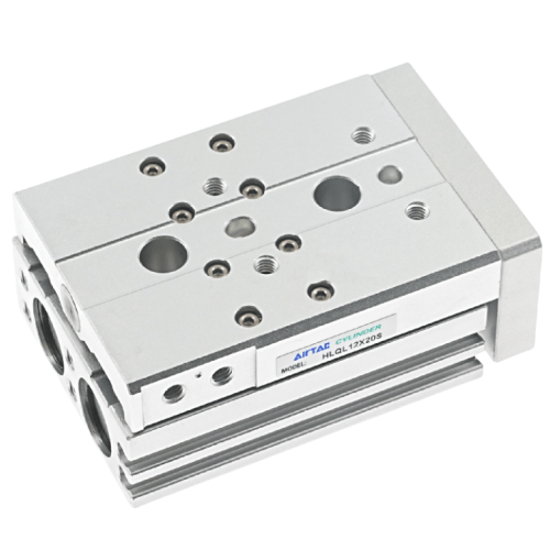
Airtac HLQL Dual Axis Precision Slide Table Cylinder HLQL20X75SB
The AirTAC Airtac HLQL Dual Axis Precision Slide Table Cylinder HLQL20X75SB is a genuine HLQ slide-table cylinder, 20 mm bore: a double-acting dual-rod air cylinder integrated with a ball-bearing guide so the table travels straight with high rigidity and low deflection. It delivers about 236 N of push at 0.5 MPa. This is the symmetrical version. A floating joint spares the rod from side torque; the magnet is fitted as standard.
- TypeSlide-table, double acting
- Guideball-bearing guide
- Bore20 mm
- Push thrust @0.5 MPa236 N
- Operating pressure0.15 - 0.7 MPa (22 - 100 psi)
- Port size1/8"
- CushionBumper (+ shock-absorber option)
- Magnet / sensorStandard; CMSH/DMSH/EMSH
- ThreadPT
- No minimum order. A single piece can be ordered.
- Ready in 3–5 business days. That is the time we take to process the order and hand it to the carrier. Transit time after that depends on the destination.
About the Airtac HLQL Dual Axis Precision Slide Table Cylinder HLQL20X75SB
The HLQL20X75SB is a symmetrical ball-bearing slide-table cylinder with a 20 mm bore and 75 mm stroke. As an HLQL-series guided table it integrates an air cylinder with a ball-bearing linear guide so the work table travels straight with low deflection. The dual-rod design doubles the thrust compared with a single-rod cylinder, while a floating joint prevents side torque on the rods. The ball-bearing guide is anti-rust and dust-proof, suited to environments where contamination is a concern. A bigger bore gives more push; this 20 mm bore provides higher thrust than the smaller bores in the HLQL range.
This is a genuine AirTAC part. A magnet is standard, and the body has magnetic-switch slots for CMSH, DMSH, or EMSH sensor switches. The adjuster code B specifies shock absorbers at both ends to cushion end-of-stroke impact. We confirm exact thrust, dimensions, and allowable load and moment values from the datasheet or on-page spec table on request.
Airtac HLQL Dual Axis Precision Slide Table Cylinder HLQL20X75SB Technical Specifications
| Model | Airtac HLQL Dual Axis Precision Slide Table Cylinder HLQL20X75SB |
|---|---|
| Type | Slide-table cylinder, double acting, dual rod |
| Series / guide | HLQL (ball-bearing guide) |
| Bore | 20 mm |
| Push thrust @0.5 MPa | 236 N |
| Port size | 1/8" (PT thread) |
| Fluid | Air, filtered to 40 um |
|---|---|
| Operating pressure | 0.15 - 0.7 MPa (22 - 100 psi) |
| Proof pressure | 1.2 MPa (175 psi) |
| Temperature | -20 to 70 C |
| Speed range | 50 - 500 mm/s (meter-out) |
| Cushion | Bumper; shock-absorber / adjustable-stopper options |
| Magnet / sensor | Standard; CMSH, DMSH, EMSH |
Specifications follow the official AirTAC HL slide-table data. Max working pressure is 0.7 MPa. The table rides on an integrated linear guide — do not apply strong impact or large moment. Allowable load and moment are published as tables and curves, and overall dimensions vary per stroke — ask us and we confirm from the datasheet.
How to choose
Choose this 20 mm bore when you need higher thrust than the 6, 8, or 12 mm bores in the HLQL range; the dual-rod ball-bearing guide delivers precise straight travel with anti-rust, dust-proof characteristics. The 75 mm stroke must be confirmed within the bore's published stroke table. The B adjuster provides shock absorbers at both ends for applications with higher impact energy at stroke limits. Thread is PT; G or NPT versions are available under different model codes. Allowable load, moment, and kinetic energy are published as tables and deflection curves - contact us for sizing confirmation against your application.
Applications
Pick-and-Place Head
Mounts a gripper or vacuum cup for precise pick-and-place of components with the ball-bearing guide keeping deflection low over the 75 mm stroke.
Small-Parts Transfer
Transfers small parts between conveyor stations with the symmetrical body allowing balanced mounting from either side.
Assembly Stage Stopper
Positions a workpiece at an assembly station where the dual shock absorbers cushion impact at both stroke ends for repeated cycling.
FAQ
What does the B adjuster code mean on the HLQL20X75SB?
The B code indicates shock absorbers at both the extension and retraction ends, providing cushioning for end-of-stroke impact in both directions. Other options include A for adjustable rubber stoppers, AS/AF for single-side rubber stoppers, and BS/BF for single-side shock absorbers. B-type adjusters are not available on bore 6.
What is the maximum operating pressure for this 20 mm bore model?
The maximum working pressure is 0.7 MPa (100 psi). The operating pressure range for this 20 mm bore is 0.15 to 0.7 MPa (22 to 100 psi). Proof pressure is 1.2 MPa (175 psi). Never operate above 0.7 MPa.