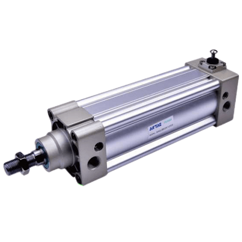
Airtac SAILB Rear Lock Cylinder SAILB160X450S
The AirTAC Airtac SAILB Rear Lock Cylinder SAILB160X450S is a genuine double-acting ISO 15552 profile cylinder with a Ø160mm bore, 450mm stroke and a built-in spring-applied, air-released mechanical lock in the back cover — it holds the load at the retracted (rod-in) stroke end even when air is lost.
- BoreØ160 mm
- Stroke450 mm
- Port sizeG3/4
- Lock positionBack cover
- Rod threadM36×2
- UnlockAir + manual
About the Airtac SAILB Rear Lock Cylinder SAILB160X450S
The AirTAC SAILB160X450-S is a double-acting ISO 15552 profile cylinder equipped with a mechanical lock in the back cover. Because it is a back-lock variant, a spring drives a locking pin into the carbon steel rod to secure the payload at the retracted stroke end. It delivers substantial thrust, pushing with 14074N and pulling with 9425N at 0.7 MPa, making it suitable for heavy-duty holding tasks.
This unit includes a magnet (-S) for position sensing with AirTAC CMSE reed and DMSE electronic switches. The lock is spring-applied and air-released, meaning it engages automatically when air is cut, ensuring power-loss safety. You can release it by supplying air to the release port or by using the manual override. Note that the variable air cushion at the locker end is 28mm, intentionally shorter than the 50mm cushion on the free end to accommodate the locking mechanism.
Airtac SAILB Rear Lock Cylinder SAILB160X450S Technical Specifications
| Model | Airtac SAILB Rear Lock Cylinder SAILB160X450S |
|---|---|
| Series | SAIL ISO 15552 cylinder with lock |
| Bore size | Ø160 mm |
| Stroke | 450 mm |
| Acting type | Double acting, with lock |
| Port size | G3/4 |
| Rod thread | M36×2 |
| Lock type | Spring-applied, air-released (back cover) |
|---|---|
| Unlock | Automatic (air) & manual |
| Operating pressure | 0.15 – 1.0 MPa |
| Temperature | -20 to +70 °C |
| Speed range | 30 – 500 mm/s |
| Cushion | Adjustable (50 mm free end / 28 mm lock end) |
| Max stroke | Up to 1500 mm |
Specifications follow the official AirTAC SAIL datasheet (ISO 15552). Confirm against the product label before installation. Port options: PT / G.
How the Lock Holds
The lock is spring-applied and air-released: a spring drives a lock pin into the rod when the release air is removed, so the load is held at the retracted (rod-in) stroke end without live pressure. Supply air to the release port to unlock automatically, or use the manual release lever.
The lock engages only when the piston reaches the stroke terminal on the back-cover side — it is a static end-of-stroke hold, not a mid-stroke clamp and not a moving-rod brake. For locking at any position along the stroke, choose a BSAI clamp-lock instead.
Theoretical Output Force (Ø160mm)
| Pressure | Push force | Pull force |
|---|---|---|
| 0.5 MPa | 10053 N | 9425 N |
| 0.7 MPa | 14074 N | — |
| Max (@1.0 MPa) | 2050 kgf | |
Cylinder thrust is separate from the lock's holding capability. Actual usable force is lower than theoretical due to friction and back-pressure — size with a margin.
Where the Airtac SAILB Rear Lock Cylinder SAILB160X450S Is Used
Vertical Power-Loss Safety
Secures heavy lifted platforms in the retracted position instantly when air pressure drops, preventing uncontrolled descent.
Heavy Clamp Holding
Maintains massive clamping force on large fabricated parts at the stroke end without consuming continuous live air pressure.
Gate and Door Locking
Locks heavy industrial safety gates securely in the closed position using the mechanical back-cover lock until released by air.
Is the Airtac SAILB Rear Lock Cylinder SAILB160X450S the Right Lock Cylinder?
Choose this 160mm bore when a 125mm cylinder lacks thrust; a 125mm bore provides 8590N push at 0.5 MPa, whereas this 160mm unit provides 10053N at the same pressure. Select SAILB to hold the rod in the retracted position, and choose SAILF if your application requires securing the extended rod-out state. If you need to clamp the load at an arbitrary mid-stroke point rather than a stroke end, select the BSAI clamp-lock cylinder instead.
The lock provides a static hold only after the piston stops at the retracted end; it is not a dynamic brake for a moving rod. Avoid using fast-exhaust valves, as back-pressure on the locker side can inadvertently release the lock; use an independent-exhaust solenoid valve. For safety-critical loads that could endanger personnel if they drop, add an independent mechanical safety measure. At 450mm stroke, guide the load externally to prevent excessive side-loading on the rod. Replacement matches require 160mm bore, 450mm stroke, back locker, PT ports, and an -S magnet.
Quick checklist
- ✓ Hold needed at the retracted (rod-in) end?
- ✓ Or lock anywhere → use BSAI
- ✓ Independent-exhaust valve fitted
- ✓ Port/thread type (PT/G)
- ✓ Extra safety measure for people
Airtac SAILB Rear Lock Cylinder SAILB160X450S FAQ
At 0.5 MPa, the push force is 10053N and the pull force is 9425N. At 0.7 MPa, the push force increases to 14074N, and at 0.9 MPa it reaches 18095N.
The lock is spring-applied and air-released, located in the back cover to hold the rod only at the retracted stroke end. It engages statically after the cylinder stops and is released automatically by supplying air to the release port or manually via a lever.
Related AirTAC Lock & Standard Cylinders
Request a Quote for Airtac SAILB Rear Lock Cylinder SAILB160X450S
Send us the quantity and destination. We confirm price, stock and lead time — usually within 7-8 hours.