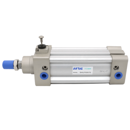
Airtac SAILF Front Locking Pneumatic Cylinder SAILF160X300
The AirTAC Airtac SAILF Front Locking Pneumatic Cylinder SAILF160X300 is a genuine double-acting ISO 15552 profile cylinder with a Ø160mm bore, 300mm stroke and a built-in spring-applied, air-released mechanical lock in the front cover — it holds the load at the extended (rod-out) stroke end even when air is lost.
- BoreØ160 mm
- Stroke300 mm
- Port sizeG3/4
- Lock positionFront cover
- Rod threadM36×2
- UnlockAir + manual
- No minimum order. A single piece can be ordered.
- Ready in 3–5 business days. That is the time we take to process the order and hand it to the carrier. Transit time after that depends on the destination.
About the Airtac SAILF Front Locking Pneumatic Cylinder SAILF160X300
The AirTAC SAILF160X300 is a double-acting ISO 15552 profile cylinder featuring a spring-applied, air-released mechanical lock housed in the front cover. This mechanism secures the rod specifically at the extended stroke end, making it ideal for heavy vertical lifting tasks. In the 160mm bore class, it generates a push force of 10053N and a pull force of 9425N at 0.5 MPa. The standard carbon steel rod handles high side-loads, while the extruded aluminum barrel integrates sensor grooves on both sides.
Because the lock physically occupies the front end, the variable air cushion on that locker side is shorter at 28mm compared to the 50mm cushion on the free end. The lock engages statically after the cylinder stops; it is not a dynamic brake for a moving rod. For position feedback, you can specify the -S magnet option to mount AirTAC CMSE reed or DMSE electronic solid-state sensors along the barrel grooves.
Airtac SAILF Front Locking Pneumatic Cylinder SAILF160X300 Technical Specifications
| Model | Airtac SAILF Front Locking Pneumatic Cylinder SAILF160X300 |
|---|---|
| Series | SAIL ISO 15552 cylinder with lock |
| Bore size | Ø160 mm |
| Stroke | 300 mm |
| Acting type | Double acting, with lock |
| Port size | G3/4 |
| Rod thread | M36×2 |
| Lock type | Spring-applied, air-released (front cover) |
|---|---|
| Unlock | Automatic (air) & manual |
| Operating pressure | 0.15 – 1.0 MPa |
| Temperature | -20 to +70 °C |
| Speed range | 30 – 500 mm/s |
| Cushion | Adjustable (50 mm free end / 28 mm lock end) |
| Max stroke | Up to 1500 mm |
Specifications follow the official AirTAC SAIL datasheet (ISO 15552). Confirm against the product label before installation. Port options: PT / G.
How the Lock Holds
The lock is spring-applied and air-released: a spring drives a lock pin into the rod when the release air is removed, so the load is held at the extended (rod-out) stroke end without live pressure. Supply air to the release port to unlock automatically, or use the manual release lever.
The lock engages only when the piston reaches the stroke terminal on the front-cover side — it is a static end-of-stroke hold, not a mid-stroke clamp and not a moving-rod brake. For locking at any position along the stroke, choose a BSAI clamp-lock instead.
Theoretical Output Force (Ø160mm)
| Pressure | Push force | Pull force |
|---|---|---|
| 0.5 MPa | 10053 N | 9425 N |
| 0.7 MPa | 14074 N | — |
| Max (@1.0 MPa) | 2050 kgf | |
Cylinder thrust is separate from the lock's holding capability. Actual usable force is lower than theoretical due to friction and back-pressure — size with a margin.
Where the Airtac SAILF Front Locking Pneumatic Cylinder SAILF160X300 Is Used
Extended Load Holding
Secures heavy lifted platforms in the rod-out position, maintaining the load safely without continuous air pressure during power loss.
Heavy Clamping End-Stop
Provides a rigid mechanical stop at the extended stroke end for high-force clamping fixtures, preventing rod retraction under vibration.
Gate and Door Safety
Locks large industrial gates in the open position, engaging automatically at the front stroke terminal to prevent accidental closure.
Is the Airtac SAILF Front Locking Pneumatic Cylinder SAILF160X300 the Right Lock Cylinder?
Choose this 160mm bore when a 125mm cylinder (providing 5734N pull at 0.5 MPa) lacks the force to lift your load, or step down from a 200mm bore if 15080N pull is excessive. Select the SAILF configuration when the load must be held safely at the rod-out extended position; if you need the load secured at the retracted rod-in position, choose the SAILB variant instead. For applications requiring the rod to be clamped at an arbitrary mid-stroke point rather than a stroke end, the BSAI clamp-lock cylinder is the correct choice.
This lock holds the load without live air pressure, but only at the front stroke terminal. Never use a fast-exhaust valve with this cylinder; instead, use an independent-exhaust solenoid valve, as back-pressure on the locker side can unintentionally release the lock. If human safety depends on the load remaining elevated, always add an independent mechanical safety measure. At a 300mm stroke, ensure external guide rails are used to prevent excessive side-loading on the rod. Replacement specifications must match the 160mm bore, 300mm stroke, front locker position, PT tapered port threads, and desired mounting style from the ISO 15552 compatible set (Basic, FA, FB, CA, CB, CR, LB, TC, FTC, TCM1, TCM2).
Quick checklist
- ✓ Hold needed at the extended (rod-out) end?
- ✓ Or lock anywhere → use BSAI
- ✓ Independent-exhaust valve fitted
- ✓ Port/thread type (PT/G)
- ✓ Extra safety measure for people
Airtac SAILF Front Locking Pneumatic Cylinder SAILF160X300 FAQ
At 0.5 MPa operating pressure, the 160mm bore provides a push force of 10053N and a pull force of 9425N. At the maximum 1.0 MPa pressure, it achieves a push force of 15708N.
The lock is spring-applied and air-released, engaging statically only after the rod reaches the extended stroke end. It does not clamp mid-stroke. To unlock, supply air to the release port for automatic release or use the manual release lever.
Related AirTAC Lock & Standard Cylinders
Request a Quote for Airtac SAILF Front Locking Pneumatic Cylinder SAILF160X300
Send us the quantity and destination. We confirm price, stock and lead time — usually within 7-8 hours.